
EBK MECHANICS OF MATERIALS
10th Edition
ISBN: 8220102744110
Author: HIBBELER
Publisher: PEARSON
expand_more
expand_more
format_list_bulleted
Concept explainers
Videos
Textbook Question
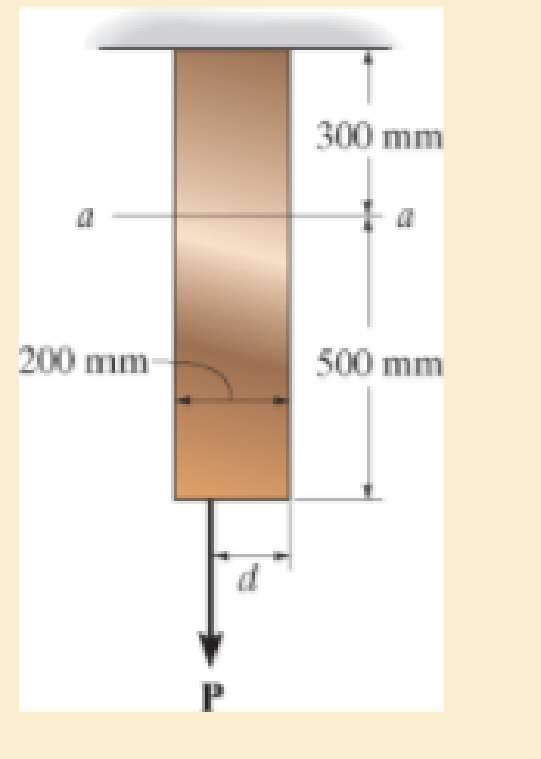
Chapter 8.2, Problem 8.18P
Determine the shortest distance d to the edge of the plate at which the force P can be applied so that it produces no compressive stresses in the plate at section a–a. The plate has a thickness of 10 mm and P acts along the centerline of this thickness.
Expert Solution & Answer
Want to see the full answer?
Check out a sample textbook solution
Students have asked these similar questions
I REPEAT!!!!! I NEED HANDDRAWING!!!!! NOT A USELESS EXPLANATION!!!! I REPEAT SUBMIT A HANDDRAWING IF YOU CANNOT UNDERSTAND THIS SKIP IT !
I need the real handdrawing complete it by adding these :
Pneumatic Valves
Each linear actuator must be controlled by a directional control valve (DCV) (e.g., 5/2 or 4/2 valve).
The bi-directional motor requires a reversible valve to change rotation direction.
Pressure Regulators & Air Supply
Include two pressure regulators as per the assignment requirement.
Show the main compressed air supply line connecting all components.
Limit Switches & Safety Features
Attach limit switches to each actuator to detect positions.
Implement a two-handed push-button safety system to control actuator movement.
Connections Between Components
Draw air supply lines linking the compressor, valves, and actuators.
Clearly label all inputs and outputs for better understanding.
An elastic bar of the length L and cross section area A is rigidly attached
to the ceiling of a room, and it supports a mass M. Due to the
acceleration of gravity g the rod deforms vertically. The deformation of
the rod is measured by the vertical displacement u(x) governed by the
following equations:
dx
(σ(x)) + b(x) = 0
PDE
σ(x) = Edx
du
Hooke's law
(1)
b(x) = gp=
body force per unit volume
where E is the constant Young's modulus, p is the density, and σ(x) the
axial stress in the rod.
g
* I u(x)
L
2
Chapter 8 Solutions
EBK MECHANICS OF MATERIALS
Ch. 8.1 - If it is subjected to an internal pressure of p =...Ch. 8.1 - If it is subjected to an internal pressure of p =...Ch. 8.1 - The thin-walled cylinder can be supported in one...Ch. 8.1 - If the inner diameter of the tank is 22 in., and...Ch. 8.1 - Air pressure in the cylinder is increased by...Ch. 8.1 - Determine the maximum force P that can be exerted...Ch. 8.1 - A boiler is constructed of 8-mm-thick steel plates...Ch. 8.1 - 88. The steel water pipe has an inner diameter of...Ch. 8.1 - The steel water pipe has an inner diameter of 12...Ch. 8.1 - The A-36-steel band is 2 in. wide and is secured...
Ch. 8.1 - The gas pipe line is supported every 20 ft by...Ch. 8.1 - A pressure-vessel head is fabricated by welding...Ch. 8.1 - An A-36-steel hoop has an inner diameter of 23.99...Ch. 8.1 - The ring, having the dimensions shown, is placed...Ch. 8.1 - The inner ring A has an inner radius r1 and outer...Ch. 8.1 - Two hemispheres having an inner radius of 2 ft and...Ch. 8.1 - In order to increase the strength of the pressure...Ch. 8.2 - Show the results on the left segment.Ch. 8.2 - Show the stress that each of these loads produce...Ch. 8.2 - Fundamental Problems F81. Determine the normal...Ch. 8.2 - Show the results in a differential element at the...Ch. 8.2 - Determine the state of stress at point A on the...Ch. 8.2 - Determine the magnitude of the load P that will...Ch. 8.2 - Determine the state of stress at point B. Show the...Ch. 8.2 - Determine the state of stress at point A on the...Ch. 8.2 - Determine the state of stress at point A on the...Ch. 8.2 - Show the results in a differential element at the...Ch. 8.2 - Determine the shortest distance d to the edge of...Ch. 8.2 - The plate has a thickness of 20 mm and P acts...Ch. 8.2 - Plot the distribution of normal stress acting...Ch. 8.2 - Also, plot the normal-stress distribution over the...Ch. 8.2 - If the allowable normal stress for the steel is...Ch. 8.2 - If the applied force P = 1.50 kip, determine the...Ch. 8.2 - Determine the maximum normal stress on the cross...Ch. 8.2 - If the wood has an allowable normal stress of...Ch. 8.2 - Determine the maximum normal stress along section...Ch. 8.2 - Sketch the stress distribution along section aa of...Ch. 8.2 - Sketch the normal-stress distribution acting over...Ch. 8.2 - Determine the state of stress at points A and B,...Ch. 8.2 - If the force of 100 N is applied to the handles,...Ch. 8.2 - Determine the stress components at point A on the...Ch. 8.2 - Determine the stress components at point B on the...Ch. 8.2 - Determine the normal stress developed at points A...Ch. 8.2 - Sketch the normal-stress distribution acting over...Ch. 8.2 - Determine the state of stress at points A and B,...Ch. 8.2 - Determine the state of stress at point A on the...Ch. 8.2 - Determine the state of stress at point B on the...Ch. 8.2 - Determine the state of stress acting at point D....Ch. 8.2 - Determine the state of stress acting at point E....Ch. 8.2 - If it is subjected to the force system shown,...Ch. 8.2 - Solve Prob.840 for point B.Ch. 8.2 - Determine the stress components acting on the...Ch. 8.2 - Determine the stress components acting on the...Ch. 8.2 - Neglect the weight of the block.Ch. 8.2 - Neglect the weight of the block.Ch. 8.2 - He is supported uniformly by two bars, each having...Ch. 8.2 - Determine the state of stress at point A, and show...Ch. 8.2 - Determine the state of stress at point B, and show...Ch. 8.2 - Determine the state of stress at point C, and show...Ch. 8.2 - Determine the maximum radius e at which the load P...Ch. 8.2 - Specify the region to which this load can be...Ch. 8.2 - Determine the smallest force P that can be applied...Ch. 8.2 - The coiled spring is subjected to a force P. If we...Ch. 8.2 - The pins at C and D are at the same location as...Ch. 8.2 - Determine the state of stress at point A, and show...Ch. 8.2 - Determine the state of stress at point B, and show...Ch. 8.2 - Determine the stress components at points A and B...Ch. 8.2 - Determine the stress components at points C and D...Ch. 8.2 - Determine the stress components in the support...Ch. 8.2 - Determine the stress components in the support...Ch. 8.2 - If the force at the ram on the clamp at D is P= 8...Ch. 8.2 - Determine the maximum ram force P that can be...Ch. 8.2 - and an outer radius of 3.00 in. If the face of the...Ch. 8.2 - for points E and F.Ch. 8.2 - Determine the stress components at points A and B...Ch. 8.2 - Solve Prob.8-65 for points C and D.Ch. 8.2 - Due to internal gearing, this causes the block to...Ch. 8.2 - Determine the state of stress at point A and show...Ch. 8.2 - Solve Prob.868 for point B.Ch. 8.2 - Determine the stress components at point A. Sketch...Ch. 8.2 - for the stress components at point B.Ch. 8.2 - Determine the state of stress at point A at...Ch. 8.2 - Determine the state of stress at point B at...Ch. 8 - If it supports a cable loading of 800 lb,...Ch. 8 - Determine the state of stress at point E on the...Ch. 8 - Determine the state of stress at point F on the...Ch. 8 - The suspender arm AE has a square cross-sectional...Ch. 8 - If the cross section of the femur at section aa...Ch. 8 - If it has a mass of 5 kg/m, determine the largest...Ch. 8 - and is used to support the vertical reactions of...Ch. 8 - and is used to support the vertical reactions of...
Additional Engineering Textbook Solutions
Find more solutions based on key concepts
Porter’s competitive forces model: The model is used to provide a general view about the firms, the competitors...
Management Information Systems: Managing The Digital Firm (16th Edition)
How does a computers main memory differ from its auxiliary memory?
Java: An Introduction to Problem Solving and Programming (8th Edition)
How is the hydrodynamic entry length defined for flow in a pipe? Is the entry length longer in laminar or turbu...
Fluid Mechanics: Fundamentals and Applications
Write a summary list of the problem-solving steps identified in the chapter, using your own words.
BASIC BIOMECHANICS
Assume a telephone signal travels through a cable at two-thirds the speed of light. How long does it take the s...
Electric Circuits. (11th Edition)
Using your text editor, enter (that is, type in) the C++ program shown in Display 1.8. Be certain to type the f...
Problem Solving with C++ (10th Edition)
Knowledge Booster


Learn more about
Need a deep-dive on the concept behind this application? Look no further. Learn more about this topic, mechanical-engineering and related others by exploring similar questions and additional content below.Similar questions
- An elastic bar of the length L and cross section area A is rigidly attached to the ceiling of a room, and it supports a mass M. Due to the acceleration of gravity g the rod deforms vertically. The deformation of the rod is measured by the vertical displacement u(x) governed by the following equations: dx (σ(x)) + b(x) = 0 PDE σ(x) = Edx du Hooke's law (1) b(x) = gp= body force per unit volume where E is the constant Young's modulus, p is the density, and σ(x) the axial stress in the rod. g * I u(x) L 2arrow_forwardمتوسعة الفرج بو عمامة المستوى رم الواجب المنزلي رقم 04 تمرین الوان حسب يتمعن العبارات الأتية : A= (+2)+(-45) B=(+13)- C = (+17)-(+13)-(-20)+(-19 D= [(-15)-(+15)]-[(+20) + هست قیم مدرج مبدؤه النقطة ة الطول :tcm A(-2,5): B(+ 2,5) ≤ C (+5) المسافتين : BAD ين الثاني لمستوي مبدؤه 8 وحدتهarrow_forwardPlease do not rely too much on AI, because its answer may be wrong. Please consider it carefully and give your own answer!!!!! You can borrow ideas from AI, but please do not believe its answer.Very very grateful! ( If you write by hand or don't use AI, I'll give you a big thumbs up ) Please do not copy other's work,i will be very very grateful!!Please do not copy other's work,i will be very very grateful!!arrow_forward
- A thin uniform rod of mass m and length 2r rests in a smooth hemispherical bowl of radius r. A moment M = mgr horizontal plane. is applied to the rod. Assume that the bowl is fixed and its rim is in the HINT: It will help you to find the length l of that portion of the rod that remains outside the bowl. M 2r Ꮎ a) How many degrees of freedom does this system have? b) Write an equation for the virtual work in terms of the angle 0 and the motion of the center of mass (TF) c) Derive an equation for the variation in the position of the center of mass (i.e., Sŕƒ) a. HINT: Use the center of the bowl as the coordinate system origin for the problem. d) In the case of no applied moment (i.e., M = 0), derive an equation that can be used to solve for the equilibrium angle of the rod. DO NOT solve the equation e) In the case of an applied moment (i.e., M: = mgr 4 -) derive an equation that can be used to solve for the equilibrium angle of the rod. DO NOT solve the equation. f) Can the angle 0 and…arrow_forwardSolve this problem and show all of the workarrow_forwardSolve this problem and show all of the workarrow_forward
- Solve this problem and show all of the workarrow_forwardPlease do not rely too much on chatgpt, because its answer may be wrong. Please consider it carefully and give your own answer. You can borrow ideas from gpt, but please do not believe its answer.Very very grateful! Please do not copy other's work,i will be very very grateful!!Please do not copy other's work,i will be very very grateful!!arrow_forward= The frame shown is fitted with three 50 cm diameter frictionless pulleys. A force of F = 630 N is applied to the rope at an angle ◊ 43°. Member ABCD is attached to the wall by a fixed support at A. Find the forces indicated below. Note: The rope is tangent to the pully (D) and not secured at the 3 o'clock position. a b •C *су G E e d BY NC SA 2013 Michael Swanbom Values for dimensions on the figure are given in the following table. Note the figure may not be to scale. Variable Value a 81 cm b 50 cm с 59 cm d 155 cm For all answers, take x as positive to the right and positive upward. At point A, the fixed support exerts a force of: A = + ĴN and a reaction couple of: →> ΜΑ Member CG is in Select an answer magnitude У as k N-m. and carries a force of N.arrow_forward
- The lower jaw AB [Purple 1] and the upper jaw-handle AD [Yellow 2] exert vertical clamping forces on the object at R. The hand squeezes the upper jaw-handle AD [2] and the lower handle BC [Orane 4] with forces F. (Member CD [Red 3] acts as if it is pinned at D, but, in a real vise-grips, its position is actually adjustable.) The clamping force, R, depends on the geometry and on the squeezing force F applied to the handles. Determine the proportionality between the clamping force, R, and the squeezing force F for the dimensions given. d3 d4 R 1 B d1 2 d2 D... d5 F 4 F Values for dimensions on the figure are given in the following table. Note the figure may not be to scale. Variable Value d1 65 mm d2 156 mm d3 50 mm 45 d4 d5 113 mm 30 mm R = Farrow_forwardA triangular distributed load of max intensity w =460 N/m acts on beam AB. The beam is supported by a pin at A and member CD, which is connected by pins at C and D respectively. Determine the reaction forces at A and C. Enter your answers in Cartesian components. Assume the masses of both beam AB and member CD are negligible. cc 040 BY NC SA 2016 Eric Davishahl W A C D -a- B Ул -b- x Values for dimensions on the figure are given in the following table. Note the figure may not be to scale. Variable Value α 5.4 m b 8.64 m C 3.24 m The reaction at A is A = i+ ĴN. λ = i+ Ĵ N. The reaction at C is C =arrow_forward56 Clamps like the one shown are commonly used in woodworking applications. This clamp has the dimensions given in the table below the figure, and its jaws are mm thick (in the direction perpendicular to the plane of the picture). a.) The screws of the clamp are adjusted so that there is a uniform pressure of P = 150 kPa being applied to the workpieces by the jaws. Determine the force carried in each screw. Hint: the uniform pressure can be modeled in 2-D as a uniform distributed load with intensity w = Pt (units of N/m) acting over the length of contact between the jaw and the workpiece. b.) Determine the minimum vertical force (parallel to the jaws) required to pull either one of the workpieces out of the clamp jaws. Use a coefficient of static friction between all contacting surfaces of μs = 0.56 and the same clamping pressure given for part (a). 2013 Michael Swanbom A B C a Values for dimensions on the figure are given in the following table. Note the figure may not be to scale.…arrow_forward
arrow_back_ios
SEE MORE QUESTIONS
arrow_forward_ios
Recommended textbooks for you
 Elements Of ElectromagneticsMechanical EngineeringISBN:9780190698614Author:Sadiku, Matthew N. O.Publisher:Oxford University Press
 Mechanics of Materials (10th Edition)Mechanical EngineeringISBN:9780134319650Author:Russell C. HibbelerPublisher:PEARSON
 Thermodynamics: An Engineering ApproachMechanical EngineeringISBN:9781259822674Author:Yunus A. Cengel Dr., Michael A. BolesPublisher:McGraw-Hill Education
 Control Systems EngineeringMechanical EngineeringISBN:9781118170519Author:Norman S. NisePublisher:WILEY
 Mechanics of Materials (MindTap Course List)Mechanical EngineeringISBN:9781337093347Author:Barry J. Goodno, James M. GerePublisher:Cengage Learning
 Engineering Mechanics: StaticsMechanical EngineeringISBN:9781118807330Author:James L. Meriam, L. G. Kraige, J. N. BoltonPublisher:WILEY
Elements Of Electromagnetics
Mechanical Engineering
ISBN:9780190698614
Author:Sadiku, Matthew N. O.
Publisher:Oxford University Press
Mechanics of Materials (10th Edition)
Mechanical Engineering
ISBN:9780134319650
Author:Russell C. Hibbeler
Publisher:PEARSON
Thermodynamics: An Engineering Approach
Mechanical Engineering
ISBN:9781259822674
Author:Yunus A. Cengel Dr., Michael A. Boles
Publisher:McGraw-Hill Education
Control Systems Engineering
Mechanical Engineering
ISBN:9781118170519
Author:Norman S. Nise
Publisher:WILEY
Mechanics of Materials (MindTap Course List)
Mechanical Engineering
ISBN:9781337093347
Author:Barry J. Goodno, James M. Gere
Publisher:Cengage Learning
Engineering Mechanics: Statics
Mechanical Engineering
ISBN:9781118807330
Author:James L. Meriam, L. G. Kraige, J. N. Bolton
Publisher:WILEY
EVERYTHING on Axial Loading Normal Stress in 10 MINUTES - Mechanics of Materials; Author: Less Boring Lectures;https://www.youtube.com/watch?v=jQ-fNqZWrNg;License: Standard YouTube License, CC-BY