
Concept explainers
Videos
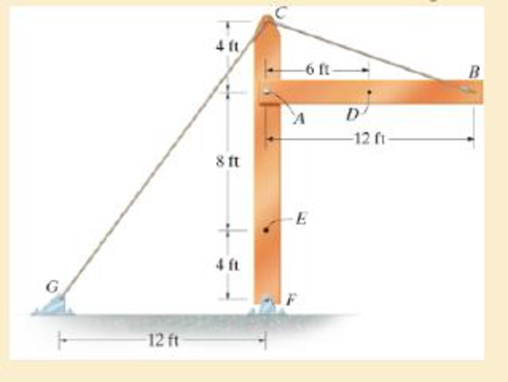
The beam AB is pin supported at A and supported by a cable BC. A separate cable CG is used to hold up the frame. If AB weighs 120 lb/ft and the column FC has a weight of 180 lb/ft, determine the resultant internal loadings acting on cross sections located at points D and E.
Answer to Problem 1.1RP
The resultant internal loadings at cross section at D are
The resultant internal loadings at cross section at E are
Explanation of Solution
Given information:
The beam AB is pin supported at A and supported by a cable BC.
The weight of the beam AB is
The weight of the column FC is
Calculation:
Find the loading at the center of the beam AB
Substitute
Convert the unit from lb to kip.
Sketch the Free Body Diagram of the beam AB shown in Figure 1.
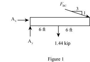
Refer to Figure 1.
Find the angle of cable BC to the horizontal
Find the tension in cable BC as shown below.
Take moment about A is Equal to zero.
Find the support reaction at A as shown below.
Apply the Equations of Equilibrium as shown below.
Summation of forces along horizontal direction is Equal to zero.
Summation of forces along vertical direction is Equal to zero.
Find the loading at the center of the beam AD
Substitute
Convert the unit from lb to kip.
Sketch the Free Body Diagram of the section for point D as shown in Figure 2.
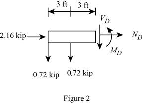
Refer to Figure 2.
Find the internal loadings as shown below.
Apply the Equations of Equilibrium as shown below.
Summation of forces along horizontal direction is Equal to zero.
Summation of forces along vertical direction is Equal to zero.
Take moment about D is Equal to zero.
Hence, the resultant internal loadings at cross section at D are
Find the loading at the center of the column FC
Substitute
Convert the unit from lb to kip.
Sketch the Free Body Diagram of the beam FC shown in Figure 3.
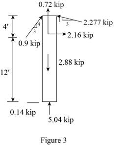
Refer to Figure 3.
Find the angle of cable CG to the horizontal.
Find the tension in cable CG as shown below.
Summation of forces along horizontal direction is Equal to zero.
Find the loading at the center of the column FE
Substitute
Convert the unit from lb to kip.
Sketch the Free Body Diagram of the section for point E as shown in Figure 4.
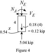
Refer to Figure 4.
Find the internal loadings as shown below.
Apply the Equations of Equilibrium as shown below.
Summation of forces along horizontal direction is Equal to zero.
Summation of forces along vertical direction is Equal to zero.
Take moment about E is Equal to zero.
Therefore, the resultant internal loadings at cross section at E are
Want to see more full solutions like this?
Chapter 1 Solutions
EBK MECHANICS OF MATERIALS
Additional Engineering Textbook Solutions
Starting Out with Java: From Control Structures through Objects (7th Edition) (What's New in Computer Science)
Degarmo's Materials And Processes In Manufacturing
Starting Out with C++: Early Objects (9th Edition)
Computer Science: An Overview (13th Edition) (What's New in Computer Science)
Introduction To Programming Using Visual Basic (11th Edition)
Starting Out with Python (4th Edition)


- Test 1 .DOCX * A File Edit View Tools Help INDUSTRIAL ENGINEERING PROGRAMME IMB 411-INDUSTRIAL LOGISTICS TEST 1- SEPTEMBER 12, 2012 Instructions: Answer all questions. Time allowed is 1.5 hours. Identify your script with your student number ONLY (Do not write your name). 1. Define the following terms (i) Logistics management (ii) Supply chain management (iii) Vertical integration in a supply chain (3 Marks) (3 Marks) (3 Marks) 2. (a) Using examples of your choice, briefly discuss the following levels of customer service (1) Pre-transaction elements (ii) Transaction elements (4 Marks) (4 Marks) (iii) Post-transaction elements (4 Marks) (b) "The challenge facing Dumelang Enterprise (Pty) Ltd is to establish the real profitability of their customers and to develop service strategies that will improve the profitability of all customers". As a logistics consultant, briefly discuss how you can advise Dumelang's customer service management. 3. (a) List the three main forms of inventory in a…arrow_forwardIt is decided to install several single-jet Pelton wheels to produce a total power of 18 MW. The available head is 246 m. The wheel rotational speed is 650 rpm and the speed ratio (❤) = 0.46. The diameter of the nozzle (jet) is limited to be 0.167 m with a Cv of 0.95. The efficiency of each turbine is 87%. Determine: (1) The number of Pelton wheels to be used, and (2) The bucket angle.arrow_forwardPlease show All work and fill it in thermodynamicsarrow_forward
- Quick solution required. My request, Don't use Ai. Mechanical engineeringarrow_forwardPlease give handwritten solution, don't use chatgpt. Fbd should be includedarrow_forward(I) [40 Points] Using centered finite difference approximations as done in class, solve the equation for O: d20 dx² + 0.010+ Q=0 subject to the boundary conditions shown in the stencil below. Do this for two values of Q: (a) Q = 0.3, and (b) Q= √(0.5 + 2x)e-sinx (cos(5x)+x-0.5√1.006-x| + e −43*|1+.001+x* | * sin (1.5 − x) + (cosx+0.001 + ex-1250+ sin (1-0.9x)|) * x - 4.68x4. For Case (a) (that is, Q = 0.3), use the stencil in Fig. 1. For Case (b), calculate with both the stencils in Fig. 1 and Fig 2. For all the three cases, show a table as well as a plot of O versus x. Discuss your results. Use MATLAB and hand in the MATLAB codes. 1 0=0 x=0 2 3 4 0=1 x=1 Fig 1 1 2 3 4 5 6 7 8 9 10 11 0=0 x=0 0=1 x=1 Fig 2arrow_forward
- Fig 2 (II) [60 Points] Using centered finite difference approximation as done in class, solve the equation: 020 020 + მx2 მy2 +0.0150+Q=0 subject to the boundary conditions shown in the stencils below. Do this for two values of Q: (a) Q = 0.3, and (b) Q = 10.5x² + 1.26 * 1.5 x 0.002 0.008. For Case (a) (that is, Q = 0.3) use Fig 3. For Case (b), use both Fig. 3 and Fig 4. For all the three cases, show a table as well as the contour plots of versus (x, y), and the (x, y) heat flux values at all the nodes on the boundaries x = 1 and y = 1. Discuss your results. Use MATLAB and hand in the MATLAB codes. (Note that the domain is (x, y)e[0,1] x [0,1].) 0=0 0=0 4 8 12 16 10 Ꮎ0 15 25 9 14 19 24 3 11 15 0=0 8-0 0=0 3 8 13 18 23 2 6 сл 5 0=0 10 14 6 12 17 22 1 6 11 16 21 13 e=0 Fig 3 Fig 4 Textbook: Numerical Methods for Engineers, Steven C. Chapra and Raymond P. Canale, McGraw-Hill, Eighth Edition (2021).arrow_forwardShip construction question. Sketch and describe the forward arrangements of a ship. Include componets of the structure and a explanation of each part/ term. Ive attached a general fore end arrangement. Simplfy construction and give a brief describion of the terms.arrow_forwardProblem 1 Consider R has a functional relationship with variables in the form R = K xq xx using show that n ✓ - (OR 1.) = i=1 2 Их Ux2 Ихэ 2 (177)² = ² (1)² + b² (12)² + c² (1)² 2 UR R x2 x3arrow_forward
- 4. Figure 3 shows a crank loaded by a force F = 1000 N and Mx = 40 Nm. a. Draw a free-body diagram of arm 2 showing the values of all forces, moments, and torques that act due to force F. Label the directions of the coordinate axes on this diagram. b. Draw a free-body diagram of arm 2 showing the values of all forces, moments, and torques that act due to moment Mr. Label the directions of the coordinate axes on this diagram. Draw a free body diagram of the wall plane showing all the forces, torques, and moments acting there. d. Locate a stress element on the top surface of the shaft at A and calculate all the stress components that act upon this element. e. Determine the principal stresses and maximum shear stresses at this point at A.arrow_forward3. Given a heat treated 6061 aluminum, solid, elliptical column with 200 mm length, 200 N concentric load, and a safety factor of 1.2, design a suitable column if its boundary conditions are fixed-free and the ratio of major to minor axis is 2.5:1. (Use AISC recommended values and round the ellipse dimensions so that both axes are whole millimeters in the correct 2.5:1 ratio.)arrow_forward1. A simply supported shaft is shown in Figure 1 with w₁ = 25 N/cm and M = 20 N cm. Use singularity functions to determine the reactions at the supports. Assume El = 1000 kN cm². Wo M 0 10 20 30 40 50 60 70 80 90 100 110 cm Figure 1 - Problem 1arrow_forward
 International Edition---engineering Mechanics: St...Mechanical EngineeringISBN:9781305501607Author:Andrew Pytel And Jaan KiusalaasPublisher:CENGAGE L