
EBK MECHANICS OF MATERIALS
10th Edition
ISBN: 8220102744110
Author: HIBBELER
Publisher: PEARSON
expand_more
expand_more
format_list_bulleted
Concept explainers
Videos
Textbook Question
Chapter 8.2, Problem 8.30P
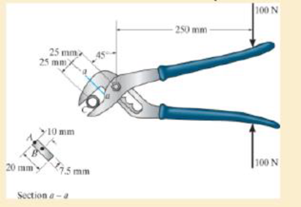
If the force of 100 N is applied to the handles, determine the state of stress at points A and B on the cross section of the jaw at section a–a. Indicate the results on an element at each point.
Expert Solution & Answer
Want to see the full answer?
Check out a sample textbook solution
Students have asked these similar questions
A 2D incompressible flow has velocitycomponents u= X^2 - 2y^2 and v=aX^b y^c
,where a, b, and c are numbers.
Find the values of a, b, and c
Find the stream function
Please can you assist with the attached question please?
(a) Find a second-order homogeneous linear ODE for which the given functions are
solutions. (b) Show linear independence by the Wronskian. (c) Solve the initial value
problem.
a. cos(5x), sin(5x), y(0) = 3, y'(0) = −5
b. e-2.5x cos(0.3x), e-2.5x sin(0.3x), y(0) = 3, y'(0) = -7.5
Chapter 8 Solutions
EBK MECHANICS OF MATERIALS
Ch. 8.1 - If it is subjected to an internal pressure of p =...Ch. 8.1 - If it is subjected to an internal pressure of p =...Ch. 8.1 - The thin-walled cylinder can be supported in one...Ch. 8.1 - If the inner diameter of the tank is 22 in., and...Ch. 8.1 - Air pressure in the cylinder is increased by...Ch. 8.1 - Determine the maximum force P that can be exerted...Ch. 8.1 - A boiler is constructed of 8-mm-thick steel plates...Ch. 8.1 - 88. The steel water pipe has an inner diameter of...Ch. 8.1 - The steel water pipe has an inner diameter of 12...Ch. 8.1 - The A-36-steel band is 2 in. wide and is secured...
Ch. 8.1 - The gas pipe line is supported every 20 ft by...Ch. 8.1 - A pressure-vessel head is fabricated by welding...Ch. 8.1 - An A-36-steel hoop has an inner diameter of 23.99...Ch. 8.1 - The ring, having the dimensions shown, is placed...Ch. 8.1 - The inner ring A has an inner radius r1 and outer...Ch. 8.1 - Two hemispheres having an inner radius of 2 ft and...Ch. 8.1 - In order to increase the strength of the pressure...Ch. 8.2 - Show the results on the left segment.Ch. 8.2 - Show the stress that each of these loads produce...Ch. 8.2 - Fundamental Problems F81. Determine the normal...Ch. 8.2 - Show the results in a differential element at the...Ch. 8.2 - Determine the state of stress at point A on the...Ch. 8.2 - Determine the magnitude of the load P that will...Ch. 8.2 - Determine the state of stress at point B. Show the...Ch. 8.2 - Determine the state of stress at point A on the...Ch. 8.2 - Determine the state of stress at point A on the...Ch. 8.2 - Show the results in a differential element at the...Ch. 8.2 - Determine the shortest distance d to the edge of...Ch. 8.2 - The plate has a thickness of 20 mm and P acts...Ch. 8.2 - Plot the distribution of normal stress acting...Ch. 8.2 - Also, plot the normal-stress distribution over the...Ch. 8.2 - If the allowable normal stress for the steel is...Ch. 8.2 - If the applied force P = 1.50 kip, determine the...Ch. 8.2 - Determine the maximum normal stress on the cross...Ch. 8.2 - If the wood has an allowable normal stress of...Ch. 8.2 - Determine the maximum normal stress along section...Ch. 8.2 - Sketch the stress distribution along section aa of...Ch. 8.2 - Sketch the normal-stress distribution acting over...Ch. 8.2 - Determine the state of stress at points A and B,...Ch. 8.2 - If the force of 100 N is applied to the handles,...Ch. 8.2 - Determine the stress components at point A on the...Ch. 8.2 - Determine the stress components at point B on the...Ch. 8.2 - Determine the normal stress developed at points A...Ch. 8.2 - Sketch the normal-stress distribution acting over...Ch. 8.2 - Determine the state of stress at points A and B,...Ch. 8.2 - Determine the state of stress at point A on the...Ch. 8.2 - Determine the state of stress at point B on the...Ch. 8.2 - Determine the state of stress acting at point D....Ch. 8.2 - Determine the state of stress acting at point E....Ch. 8.2 - If it is subjected to the force system shown,...Ch. 8.2 - Solve Prob.840 for point B.Ch. 8.2 - Determine the stress components acting on the...Ch. 8.2 - Determine the stress components acting on the...Ch. 8.2 - Neglect the weight of the block.Ch. 8.2 - Neglect the weight of the block.Ch. 8.2 - He is supported uniformly by two bars, each having...Ch. 8.2 - Determine the state of stress at point A, and show...Ch. 8.2 - Determine the state of stress at point B, and show...Ch. 8.2 - Determine the state of stress at point C, and show...Ch. 8.2 - Determine the maximum radius e at which the load P...Ch. 8.2 - Specify the region to which this load can be...Ch. 8.2 - Determine the smallest force P that can be applied...Ch. 8.2 - The coiled spring is subjected to a force P. If we...Ch. 8.2 - The pins at C and D are at the same location as...Ch. 8.2 - Determine the state of stress at point A, and show...Ch. 8.2 - Determine the state of stress at point B, and show...Ch. 8.2 - Determine the stress components at points A and B...Ch. 8.2 - Determine the stress components at points C and D...Ch. 8.2 - Determine the stress components in the support...Ch. 8.2 - Determine the stress components in the support...Ch. 8.2 - If the force at the ram on the clamp at D is P= 8...Ch. 8.2 - Determine the maximum ram force P that can be...Ch. 8.2 - and an outer radius of 3.00 in. If the face of the...Ch. 8.2 - for points E and F.Ch. 8.2 - Determine the stress components at points A and B...Ch. 8.2 - Solve Prob.8-65 for points C and D.Ch. 8.2 - Due to internal gearing, this causes the block to...Ch. 8.2 - Determine the state of stress at point A and show...Ch. 8.2 - Solve Prob.868 for point B.Ch. 8.2 - Determine the stress components at point A. Sketch...Ch. 8.2 - for the stress components at point B.Ch. 8.2 - Determine the state of stress at point A at...Ch. 8.2 - Determine the state of stress at point B at...Ch. 8 - If it supports a cable loading of 800 lb,...Ch. 8 - Determine the state of stress at point E on the...Ch. 8 - Determine the state of stress at point F on the...Ch. 8 - The suspender arm AE has a square cross-sectional...Ch. 8 - If the cross section of the femur at section aa...Ch. 8 - If it has a mass of 5 kg/m, determine the largest...Ch. 8 - and is used to support the vertical reactions of...Ch. 8 - and is used to support the vertical reactions of...
Additional Engineering Textbook Solutions
Find more solutions based on key concepts
How does a computers main memory differ from its auxiliary memory?
Java: An Introduction to Problem Solving and Programming (8th Edition)
Assume a telephone signal travels through a cable at two-thirds the speed of light. How long does it take the s...
Electric Circuits. (11th Edition)
How is the hydrodynamic entry length defined for flow in a pipe? Is the entry length longer in laminar or turbu...
Fluid Mechanics: Fundamentals and Applications
CONCEPT QUESTIONS
15.CQ3 The ball rolls without slipping on the fixed surface as shown. What is the direction ...
Vector Mechanics for Engineers: Statics and Dynamics
17–1C A high-speed aircraft is cruising in still air. How does the temperature of air at the nose of the aircra...
Thermodynamics: An Engineering Approach
Knowledge Booster


Learn more about
Need a deep-dive on the concept behind this application? Look no further. Learn more about this topic, mechanical-engineering and related others by exploring similar questions and additional content below.Similar questions
- Solve the IVP. a. y" 16y 17e* ; = y(0) = 6, y'(0) = -2 b. (D² + 41)y = sin(t) + ½ sin(3t) + sin(t) ; y(0) = 0, y'(0) : = 35 31arrow_forwardFind the general solution. a. y' 5y = 3ex - 2x + 1 - b. y" +4y' + 4y = e¯*cos(x) c. (D² + I)y = cos(wt), w² # 1arrow_forwardhandwritten solutions, please!!arrow_forward
- > Homework 4 - Spring 2025.pdf Spring 2025.pdf k 4 - Spring 2025.pdf (447 KB) Due: Thursday, February 27 Page 1 > of 2 ZOOM 1. A simply supported shaft is shown in Figure 1 with wo = 25 N/cm and M = 20 N cm. Use singularity functions to determine the reactions at the supports. Assume EI = 1000 kN cm². M Wo 0 10 20 30 40 50 60 70 80 90 100 110 cm Figure 1 - Problem 1 2. A support hook was formed from a rectangular bar. Find the stresses at the inner and outer surfaces at sections just above and just below O-B. 210 mmarrow_forwardA distillation column with a total condenser and a partial reboiler is separating ethanol andwater at 1.0 atm. Feed is 0.32 mol fraction ethanol and it enters as a saturated liquid at 100mol/s on the optimum plate. The distillate product is a saturated liquid with 80 mol% ethanol.The condenser removes 5615 kW. The bottoms product is 0.05 mol fraction ethanol. AssumeCMO is valid.(a) Find the number of equilibrium stages for this separation. [6 + PR](b) Find how much larger the actual reflux ratio, R, used is than Rmin, i.e. R/Rmin. [3]Note: the heats of vaporization of ethanol and water are λe = 38.58 and λw = 40.645 arrow_forwardWe have a feed that is a binary mixture of methanol and water (60.0 mol% methanol) that issent to a system of two flash drums hooked together. The vapor from the first drum is cooled,which partially condenses the vapor, and then is fed to the second flash drum. Both drumsoperate at 1.0 atm and are adiabatic. The feed to the first drum is 1000 kmol/hr. We desire aliquid product from the first drum that is 35.0 mol% methanol. The second drum operates at afraction vaporized of (V/F)2 = 0.25.(a) Find the liquid flow rate leaving the first flash drum, L1 (kmol/hr). [286 kmol/hr](b) Find the vapor composition leaving the second flash drum, y2. [0.85]arrow_forward
- = The steel curved bar shown has rectangular cross-section with a radial height h = 6 mm and thickness b = 4mm. The radius of the centroidal axis is R = 80 mm. A force P = 10 N is applied as shown. Assume the steel modulus of 207,000 MPa and G = 79.3(103) MPa, repectively. elasticity and shear modulus E = Find the vertical deflection at point B. Use Castigliano's method for a curved flexural member and since R/h > 10, neglect the effect of shear and axial load, thereby assuming that deflection is due to merely the bending moment. Note the inner and outer radii of the curves bar are: r = 80 + ½ (6) = 83 mm, r₁ = 80 − ½ (6) = 77 mm 2 2 Sπ/2 sin² 0 d = √π/² cos² 0 d0 = Π 0 4 大 C R B Parrow_forwardThe steel eyebolt shown in the figure is loaded with a force F = 75 lb. The eyebolt is formed from round wire of diameter d = 0.25 in to a radius R₁ = 0.50 in in the eye and at the shank. Estimate the stresses at the inner and outer surfaces at section A-A. Notice at the section A-A: r₁ = 0.5 in, ro = 0.75 in rc = 0.5 + 0.125 = 0.625 in Ri 200 F FAarrow_forwardI have the fallowing question and solution from a reeds naval arc book. Im just confused as to where this answer came from and the formulas used. Wondering if i could have this answer/ solution broken down and explained in detail. A ship of 7000 tonne displacement has a waterplane areaof 1500 m2. In passing from sea water into river water of1005 kg/m3 there is an increase in draught of 10 cm. Find the Idensity of the sea water. picture of the "answer" is attachedarrow_forward
- Problem A2 long steel tube has a rectangular cross-section with outer dimensions of 20 x 20 mm and a uniform wall thickness of 2. The tube is twisted along its length with torque, T. The tube material is 1045 CD steel with shear yield strength of S,, =315 MPa. Assume shear modulus, G = 79.3GPa. (a) Estimate the maximum torque that can be applied without yielding (b) Estimate the torque required to produce 5 degrees total angle of twist over the length of the tube. (c) What is the maximum torque that can be applied without yielding, if a solid rectangular shaft with dimensions of 20 x 20 is used? You may use the exact solution.arrow_forwardA simply supported beam is loaded as shown. Considering symmetry, the reactions at supports A and B are R₁ = R₂ = wa 2 Using the singularity method, determine the shear force V along the length of the beam as a function of distance x from the support A. A B Ir. 2a За W C R₁₂ x 2. Using the singularity method, determine the bending M along the length of the beam as a function of distance x, from the support A. 3. Using the singularity method, determine the beam slope and deflection along the length of the beam as a function of the distance x, from the support A. Assume the material modulus of elasticity, E and the moment of inertia of the beam cross-section, I are given.arrow_forwardA steel tube, 2 m long, has a rectangular cross-section with outer dimensions of 20 × 30 mm and a uniform wall thickness of 1 mm. The tube is twisted along its length with torque, T. The tube material is 1018 CD steel with shear yield strength of Ssy =185 MPa. Assume shear modulus, G = 79.3GPa. (a) Estimate the maximum torque that can be applied without yielding.- (b) Estimate the torque required to produce 3 degrees total angle of twist over the length of the tube. (c) What is the maximum torque that can be applied without yielding, if a solid rectangular shaft with dimensions of 20 x 30 mm is used? You may use the exact solution:arrow_forward
arrow_back_ios
SEE MORE QUESTIONS
arrow_forward_ios
Recommended textbooks for you
 Elements Of ElectromagneticsMechanical EngineeringISBN:9780190698614Author:Sadiku, Matthew N. O.Publisher:Oxford University Press
 Mechanics of Materials (10th Edition)Mechanical EngineeringISBN:9780134319650Author:Russell C. HibbelerPublisher:PEARSON
 Thermodynamics: An Engineering ApproachMechanical EngineeringISBN:9781259822674Author:Yunus A. Cengel Dr., Michael A. BolesPublisher:McGraw-Hill Education
 Control Systems EngineeringMechanical EngineeringISBN:9781118170519Author:Norman S. NisePublisher:WILEY
 Mechanics of Materials (MindTap Course List)Mechanical EngineeringISBN:9781337093347Author:Barry J. Goodno, James M. GerePublisher:Cengage Learning
 Engineering Mechanics: StaticsMechanical EngineeringISBN:9781118807330Author:James L. Meriam, L. G. Kraige, J. N. BoltonPublisher:WILEY
Elements Of Electromagnetics
Mechanical Engineering
ISBN:9780190698614
Author:Sadiku, Matthew N. O.
Publisher:Oxford University Press
Mechanics of Materials (10th Edition)
Mechanical Engineering
ISBN:9780134319650
Author:Russell C. Hibbeler
Publisher:PEARSON
Thermodynamics: An Engineering Approach
Mechanical Engineering
ISBN:9781259822674
Author:Yunus A. Cengel Dr., Michael A. Boles
Publisher:McGraw-Hill Education
Control Systems Engineering
Mechanical Engineering
ISBN:9781118170519
Author:Norman S. Nise
Publisher:WILEY
Mechanics of Materials (MindTap Course List)
Mechanical Engineering
ISBN:9781337093347
Author:Barry J. Goodno, James M. Gere
Publisher:Cengage Learning
Engineering Mechanics: Statics
Mechanical Engineering
ISBN:9781118807330
Author:James L. Meriam, L. G. Kraige, J. N. Bolton
Publisher:WILEY
Hand Tools; Author: UCI Media;https://www.youtube.com/watch?v=4o0tqF0jDdo;License: Standard Youtube License