
Concept explainers
Videos
Three loops, all made of the same type of wire, are placed near the ends of identical solenoids as shown. The solenoids are connected in series. Assume that the magnetic field near the end of each of the solenoids is uniform.
LOOP 2 consists of two turns of a single wire that is twice as long as the wire used to make loop 1. Loop 3 is made of a single wire that is half as long as the wire used to make loop 1.
Just after the switch has been closed, the current through the battery begins to increase. The following questions concern the period of time during which the current is increasing.
1. Let
2. Let R represent the resistance of loop 1. Find the resistance of each of the other loops in terms of R. Explain.
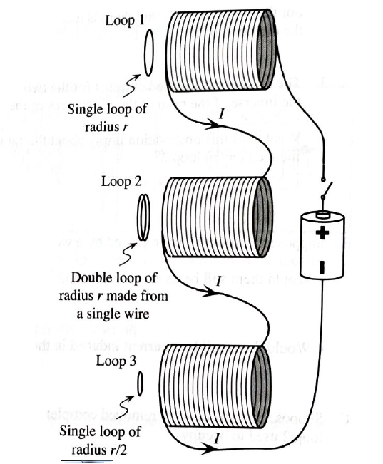
3. Find the current induced through the wire of each of the loops in terms of E and R.

Trending nowThis is a popular solution!

Learn your wayIncludes step-by-step video

Chapter 8 Solutions
Tutorials in Introductory Physics
Additional Science Textbook Solutions
Campbell Biology: Concepts & Connections (9th Edition)
Chemistry: A Molecular Approach (4th Edition)
Microbiology: An Introduction
Campbell Biology (11th Edition)
Organic Chemistry (8th Edition)
Genetic Analysis: An Integrated Approach (3rd Edition)


- No chatgpt pls will upvote Already got wrong chatgpt answer .arrow_forwardUse the following information to answer the next question. Two mirrors meet an angle, a, of 105°. A ray of light is incident upon mirror A at an angle, i, of 42°. The ray of light reflects off mirror B and then enters water, as shown below: A Incident ray at A Note: This diagram is not to scale. Air (n = 1.00) Water (n = 1.34) Barrow_forwardUse the following information to answer the next question. Two mirrors meet an angle, a, of 105°. A ray of light is incident upon mirror A at an angle, i, of 42°. The ray of light reflects off mirror B and then enters water, as shown below: A Incident ray at A Note: This diagram is not to scale. Air (n = 1.00) Water (n = 1.34) Barrow_forward
- Good explanation it sure experts solve it.arrow_forwardNo chatgpt pls will upvote Asaparrow_forwardA satellite has a mass of 100kg and is located at 2.00 x 10^6 m above the surface of the earth. a) What is the potential energy associated with the satellite at this loction? b) What is the magnitude of the gravitational force on the satellite?arrow_forward
- No chatgpt pls will upvotearrow_forwardCorrect answer No chatgpt pls will upvotearrow_forwardStatistical thermodynamics. The number of imaginary replicas of a system of N particlesa) cannot be greater than Avogadro's numberb) must always be greater than Avogadro's number.c) has no relation to Avogadro's number.arrow_forward
- Lab-Based Section Use the following information to answer the lab based scenario. A student performed an experiment in an attempt to determine the index of refraction of glass. The student used a laser and a protractor to measure a variety of angles of incidence and refraction through a semi-circular glass prism. The design of the experiment and the student's results are shown below. Angle of Incidence (°) Angle of Refraction (º) 20 11 30 19 40 26 50 31 60 36 70 38 2a) By hand (i.e., without using computer software), create a linear graph on graph paper using the student's data. Note: You will have to manipulate the data in order to achieve a linear function. 2b) Graphically determine the index of refraction of the semi-circular glass prism, rounding your answer to the nearest hundredth.arrow_forwardUse the following information to answer the next two questions. A laser is directed at a prism made of zircon (n = 1.92) at an incident angle of 35.0°, as shown in the diagram. 3a) Determine the critical angle of zircon. 35.0° 70° 55 55° 3b) Determine the angle of refraction when the laser beam leaves the prism.arrow_forwardUse the following information to answer the next two questions. A laser is directed at a prism made of zircon (n = 1.92) at an incident angle of 35.0°, as shown in the diagram. 3a) Determine the critical angle of zircon. 35.0° 70° 55 55° 3b) Determine the angle of refraction when the laser beam leaves the prism.arrow_forward
 Principles of Physics: A Calculus-Based TextPhysicsISBN:9781133104261Author:Raymond A. Serway, John W. JewettPublisher:Cengage Learning
 Physics for Scientists and Engineers with Modern ...PhysicsISBN:9781337553292Author:Raymond A. Serway, John W. JewettPublisher:Cengage Learning
 Physics for Scientists and EngineersPhysicsISBN:9781337553278Author:Raymond A. Serway, John W. JewettPublisher:Cengage Learning
 Physics for Scientists and Engineers: Foundations...PhysicsISBN:9781133939146Author:Katz, Debora M.Publisher:Cengage Learning
 Physics for Scientists and Engineers, Technology ...PhysicsISBN:9781305116399Author:Raymond A. Serway, John W. JewettPublisher:Cengage Learning