Concept explainers
Videos
|
|
|
|
|
|
||||
|
|
|
|
|
|
||||
|
|
|
|
|
|
||||
|
|
|
|
|
|
||||
|
|
|
|
|
|
||||
|
|
|
|
|
|
||||
|
|
|
|
|
|
||||
|
|
|
|
|
|
||||
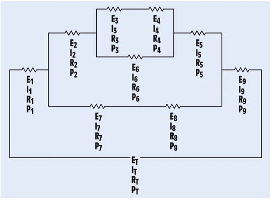
FIGURE 8-26 A combination circuit.
The unknown values in the circuit.
Answer to Problem 8PP
| ET = 24.04 V | E1 = 3.4V | E2 = 4.8 V | E3 = 0.478 V | E4 = 1.248 V |
| IT = 24.02mA | I1 = 24.02mA | I2 = 9.614 mA | I3 = 3.854 mA | I4 = 3.854 mA |
| RT = 942 Ω | R1 = 144 Ω | R2 = 499 Ω | R3 = 124Ω | R4 = 324 Ω |
| PT = 0.576 W | P1 = 0.0806W | P2 = 0.0461W | P3 = 0.00184W | P4 = 0.00481W |
| E5 = 2.11 V | E6 = 1.726V | E7 = 3.6 V | E8 = 5.04V | E9 = 12 V |
| I5 = 9.614 mA | I6 = 5.76 mA | I7 = 14.41 mA | I8 = 14.41 mA | I9 = 24.02 mA |
| R5 = 220 Ω | R6 = 300Ω | R7 = 86Ω | R8 = 360Ω | R9 = 500 Ω |
| P5 = 0.0203 W | P6 = 0.00995 W | P7 = 0.0518W | P8 = 0.0726W | P9 = 0.288 W |
Explanation of Solution
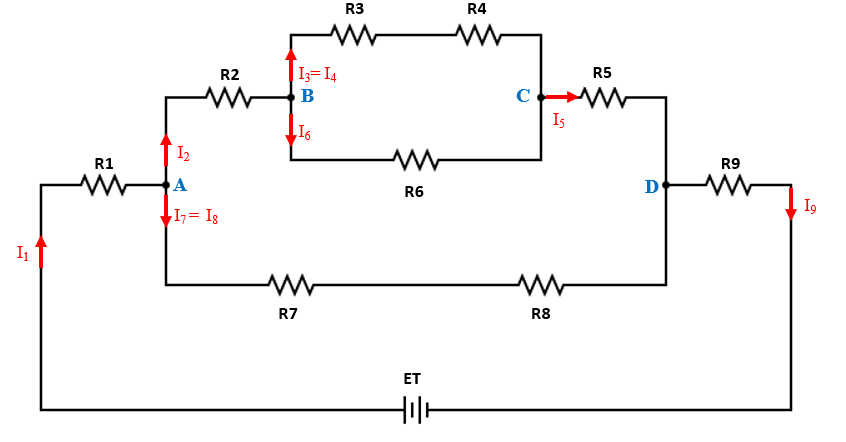
In the given question,
Current flowing through R1 is denoted by I1
Current flowing through R2is denoted by I2
Current flowing through R3 and R4 is denoted by I3(= I4)
Current flowing through R5 is denoted by I5
Current flowing through R6 is denoted by I6
Current flowing through R7 and R8 is denoted by I7 (= I8)
Current flowing through R9is denoted by I9
The total power consumed by the circuit is equal to sum of power consumed by individual resistors. Hence,
Using the voltage E4 and Power P4, we calculate resistance R4 and current I4
Since R3 and R4 are in series, the same current flows through both. Therefore, I3=I4=3.854 mA
Using the current I3 and resistance R3 find the voltage E3
Since R6 is in parallel with series combination of R3 and R4. Hence,
E6= 0.478 + 1.248 =1.726 V
Using the voltage E6 and Power P6, we calculate resistance R6 and current I6
At node B,
Using P2 and I2, we calculate R2
Using P2 and I2, we calculate E2
Since the incoming current in a network is equal to the outgoing current, current at node B= current at node C: I2=I5=9.614 mA
Using the voltage E5 and Power P5, we calculate resistance R5 and current I5
The total voltage drop across R7 and R8 i.e. E7 and E8 will be
The total power consumed in the branch containing resistors R7 and R8 will be 0.0518+0.0726 = 0.1244 W
Using the total power consumed and the total voltage, we can compute the total current in the network of R7 and R8.
Using the voltage and Power, we calculate R7, R8 and current I7, I8
At node A,
Since the incoming current in a network is equal to the outgoing current, current at node A=current at node D: I1 = I9 =IT=24.02 mA
Using the current I1 and Power P1, we calculate resistance R1 and voltage E1
Using the current I9 and Power P9, we calculate resistance R9 and voltage E9
Total voltage applied across the network will be,
Want to see more full solutions like this?
Chapter 8 Solutions
Mindtap Electrical, 4 Terms (24 Months) Printed Access Card For Herman's Delmar's Standard Textbook Of Electricity, 6th (mindtap Course List)


- Which of the following statement is TRUE? 1. In RISC processors, each instruction requires only two clock cycles to complete, resulting in consistent execution time 2. RISC has more transistors and fewer registers 3. RISC has more registers and fewer transistorsarrow_forwardDifferentiate between JFET and BJT.arrow_forwardGive relation between αdc and βdc.arrow_forward
- Figure 1 shows a half-wave controlled rectifier which is supplied by a Vin = 120 Vrms voltage source. Assume that the load resistance is R = 10 2. Determine: a) The firing angle a of the thyristor to produce an average output voltage 50Vdc. Vin=Vmsinoot b) The average power Po absorbed by the load R. Figure 1 R = 1092arrow_forwardQ1. What is power dissipation in the Zener diode circuit given for a) RL=100 Ohm ? b) RL=∞arrow_forwardThe one-line diagram of an unloaded power system is shown below. Reactances of the two sections of transmission line are shown on the diagram. The generators and transformers are rated as follows: 20 MVA, 13.8 kV, X = 0.20 p.u Generator 1: Generator 2: Generator 3: 30 MVA, 18 kV, X = 0.20 p.u Transformer Ti: Transformer T2: 30 MVA, 20 kV, X = 0.20 p.u 25 MVA, 220Y/13.8A kV, X = 10% Three single-phase units each rated 10 MVA, 127/18 kV, X = 10% HT sides connected in wye Transformer T3: LT sides connected in delta 35 MVA, 220Y/22Y KV, X = 10% j80 Q j100 Q Line 1 Line 2 T₁ T₂ Draw the impedance diagram with all reactances marked in per unit. Choose a base of 50 MVA, 13.8 kV in the circuit of generator 1.arrow_forward
 Delmar's Standard Textbook Of ElectricityElectrical EngineeringISBN:9781337900348Author:Stephen L. HermanPublisher:Cengage Learning