
Concept explainers
Videos
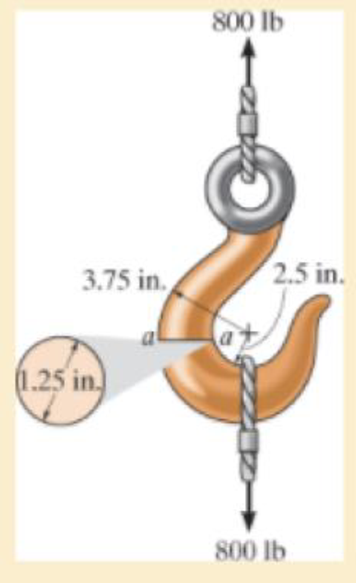
If it supports a cable loading of 800 lb, determine the maximum normal stress at section a–a and sketch the stress distribution acting over the cross section. Use the curved-beam formula to calculate the bending stress.
The maximum tensile stress
The maximum compressive stress
To sketch:
The stress distribution over the cross section.
Answer to Problem 8.74RP
The maximum tensile stress
The maximum compressive stress
Explanation of Solution
Given information:
The force in the cable is 800 lb.
Diameter of the circular is 1.25 in.
Calculation:
Expression to find the location of neutral
Here, R is the location of neutral axis, A is the cross sectional area of the member, r is the arbitrary position, and
Determine the radius
Here, d is the diameter of the circular cross section.
Substitute 1.25 in. for d in Equation (2).
Determine the area
Here, r is the radius of the circular cross section.
Substitute 0.625 in. for r in Equation (3).
Determine the value of
Here, c is the radius of cross section and
Find the distance measured from the center of curvature to the centroid of the cross section
Substitute 0.625 in. for c and 3.125 in. for
Substitute
Sketch the cross section of eye hook as shown in Figure 1.
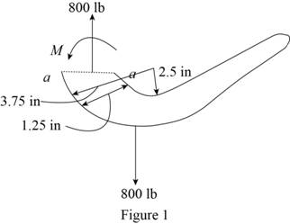
Let the moment acting at the section be M.
Express to the value of M as shown below:
Here, F is the load and R is the radius.
Determine the bending stress
Here, M is the applied moment and P is the applied load.
Substitute
Determine the maximum tensile stress
Hence, the maximum tensile stress
Determine the maximum compressive stress
Substitute
Hence, the maximum compressive stress
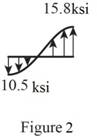
Sketch the stress distribution (tensile and compressive stress) along the cross section as shown in Figure 2.
Want to see more full solutions like this?
Chapter 8 Solutions
Mechanics of Materials


- Consider a very long, slender rod. One end of the rod is attached to a base surface maintained at Tb, while the surface of the rod is exposed to an air temperature of 400°C. Thermocouples imbedded in the rod at locations 25 mm and 120 mm from the base surface register temperatures of 325°C and 375°C, respectively. NOTE: This is a multi-part question. Once an answer is submitted, you will be unable to return to this part. . x1 32 x Calculate the rod base temperature (°C). The rod base temperature is °C. Air T∞arrow_forward(read image)arrow_forwardThis is a tilt and rotation question. Here are notes attached for reference. ONLY UPLOAD A SOLUTION IF YOU ARE SURE ABOUT THE ANSWER PLEASE.arrow_forward
- What is the difference between true stress/strain and engineering stess/strain? And how do I calculate them?arrow_forwardA rotating shaft of 20 mm diameter is simply supported. The shaft is loaded with a transverse load of 10 kN as shown in the figure. The shaft is made from AISI 1095 hot-rolled steel. The surface has been machined. The shaft operate at temperature T = 450 °C. Consider a reliability factor of 95%. Determine (a) Calculate the reaction forces R, and R₂ (2 points) (b) Draw the shear force and bending moment diagrams and determine the maximum bending moment and shear force. (6 points) 200 mm 20 mm 10,000 N -50 mm- A Not to scale. (c) Determine the critical location of the shaft and the maximum effective stresses. (3 points) (d) Calculate the safety factor against yielding. Does the shaft undergo local yielding? (2 points) (e) Determined the endurance limit, adjusted as necessary with Marin factors. (12 points) (f) Calculate the fatigue factor of safety based on achieving infinite life. (2 points) (g) If the fatigue factor of safety is less than 1 (hint: it should be for this problem), then…arrow_forward(read image)arrow_forward
- (read image)arrow_forward6: Refer to the figure.Given: W1 = 200 kN/m; W2 = 300 kN/m; L1 = 2 m; L2 = 3 m; L3 = 2 m(a) Calculate the total length L so that the resulting upward pressureq is uniform. (b) draw the shear and moment diagram and determinethe maximum shear, maximum positive and negative bendingmoments.arrow_forwardA six cylinder, four-stroke diesel engine develops a power of 200 kW at 2000 rpm. The bsfc is 0.2 kW/kg h of fuel with 34.9° API. The fuel is injected at an average pressure of 350 bar and the pressure in the combustion chamber is 40 bar. Assuming Ca for injector 0.75 and the atmospheric pressure 1 bar. Determine the period of injection in seconds if the total orifice area required per injector is 0.4876 × 10⁻⁶ m².arrow_forward
- Trieed a detailed drawing Win explanatio LL Antsmi 1981x pu + 96252 اه 6. The Pre-combustion chamber design engines employ nozzle type commonly referred to as a ....... a. inward-opening nozzle b. multiple-hole nozzle. c. pintle nozzle. d. none of these. 7. If the temperature of the spark plug tip is less than 350 °C, ......... a. the plug might not work. b. the carbon deposits would increase. 8. Port injection sprays fuel....... c. pre-ignition will occur. d. none of these. a. towards the intake valve. b. in the engine cylinder. c. in the throttle body assembly. d. none of these. 9. When the fuel-air mixture changed from best power to a richer ratio, the spark advance should be........ a. increased. b. decreased. c. left unchanged. d. none of these. d. none of these. 10. Spark plugs are classified as hot plugs and cold plugs depending upon ........ a. spark gap. b. the type of plug c. the operating temperature insulator. range of the electrode tip. ---20125 750 x2.01 SP 5.arrow_forwardA 1. How does the octane number (O.N.) of the fuel a. Higher ignition advance is required for a high O.N. fuel. b. Higher ignition retard is required for a high O.N. fuel. affect spark ing:d. Nou does not affect spark timing. c. The octane number 2. How does the ignition system account for load change? these. of a. The throttle b. The vacuum ignition governor c. The mechanism of d. None of is wide opened. provide additional spark advance at part throttle positions. centrifugal advance does the job. these. 3. In the common rail fuel system the fuel is metered by ........ a. low pressure pump. b. injectors. c. high pressure pump. d. none of these. 4.......... is the time period, measured in degrees of cam rotation, during which the contact points remain closed between each opening. a. Distributor. b. Dwell. c. ECU. d. none of these. 5. The trigger wheel in TCI system replaces the ......... used in a contact breaker distributor. a. pickup coil. b. distributor cam. c. condenser. 750 x2.01…arrow_forwarda い يكا 4 +91- pu Answer the following statements by true or false, giving the reason for your answer: 1. Injection pressure in CI engines should be sufficiently high. 2. The purpose of the condenser in battery ignition system is to prevent spark in the ignition coil assembly. 3. An idling engine requires lean mixture of fuel and air. 4. Factors which decide optimum engine firing order are engine vibration, engine cooling and back pressure. 5. It is the duty of the header to control over speeding during CI engine operation when drastic reduction in load occurs. ---20125 750 x2.01 SParrow_forward
 Mechanics of Materials (MindTap Course List)Mechanical EngineeringISBN:9781337093347Author:Barry J. Goodno, James M. GerePublisher:Cengage Learning