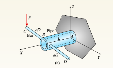
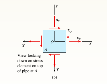
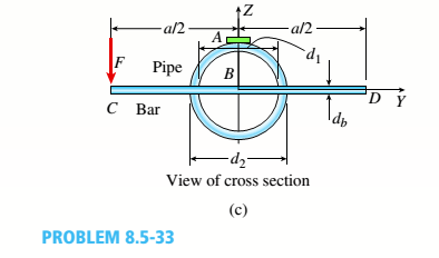
A plumber's valve wrench is used to replace valves in plumbing fixtures. A simplified model of the wrench (see figure part a) consists of pipe AB (length L. outer diameter D inner diameter dy), which is fixed at A and has holes of a diameter d h on either side of the pipe at B. A solid, cylindrical bar CBD (lengths, diameter^) is inserted into the holes at B and only one force F = 55 lb is applied in the -Z direction at C to loosen the fixture valve at A (see figure part c). Let G = 11,800 ksi, v = 0.30, L = 4 in., a = 4.5 in., d 2 = 1.25 in., d x = 1 in., and d h = 0.25 in. Find the state of plane stress on the top of the pipe near A (at coordinates A" = 0,Y = Q,Z = d->12), and show all stresses on a plane stress element (see figure part b). Compute the principal stresses and maximum shear stress, and show them on properly rotated stress elements
A plumber's valve wrench is used to replace valves in plumbing fixtures. A simplified model of the wrench (see figure part a) consists of pipe AB (length L. outer diameter D inner diameter dy), which is fixed at A and has holes of a diameter d h on either side of the pipe at B. A solid, cylindrical bar CBD (lengths, diameter^) is inserted into the holes at B and only one force F = 55 lb is applied in the -Z direction at C to loosen the fixture valve at A (see figure part c). Let G = 11,800 ksi, v = 0.30, L = 4 in., a = 4.5 in., d 2 = 1.25 in., d x = 1 in., and d h = 0.25 in. Find the state of plane stress on the top of the pipe near A (at coordinates A" = 0,Y = Q,Z = d->12), and show all stresses on a plane stress element (see figure part b). Compute the principal stresses and maximum shear stress, and show them on properly rotated stress elements
Solution Summary: The author explains the state of plane stress on the top of the pipe near A and the principle and maximum shear stress.
A plumber's valve wrench is used to replace valves in plumbing fixtures. A simplified model of the wrench (see figure part a) consists of pipe AB (length L. outer diameter D inner diameter dy), which is fixed at A and has holes of a diameter dhon either side of the pipe at B. A solid, cylindrical bar CBD (lengths, diameter^) is inserted into the holes at B and only one force F = 55 lb is applied in the -Z direction at C to loosen the fixture valve at A (see figure part c). Let G = 11,800 ksi, v = 0.30, L = 4 in., a = 4.5 in., d2= 1.25 in., dx= 1 in., and dh= 0.25 in. Find the state of plane stress on the top of the pipe near A (at coordinates A" = 0,Y = Q,Z = d->12), and show all stresses on a plane stress element (see figure part b). Compute the principal stresses and maximum shear stress, and show them on properly rotated stress elements
The net force exerted on the piston by the exploding fuel-air mixture
and friction is 5 kN to the left. A clockwise couple M = 200 N-m acts on the crank AB.
The moment of inertia of the crank about A is 0.0003 kg-m2
. The mass of the
connecting rod BC is 0.36 kg, and its center of mass is 40 mm from B on the line from B
to C. The connecting rod’s moment of inertia about its center of mass is 0.0004 kg-m2
.
The mass of the piston is 4.6 kg. The crank AB has a counterclockwise angular velocity
of 2000 rpm at the instant shown. Neglect the gravitational forces on the crank,
connecting rod, and piston – they still have mass, just don’t include weight on the FBDs.
What is the piston’s acceleration?
Solve only no 1 calculations,the one with diagram,I need handwritten expert solutions
Problem 3
•
Compute the coefficient matrix and the right-hand side of the n-parameter Ritz approximation of the
equation
d
du
(1+x)·
= 0 for 0 < x < 1
dx
dx
u (0)
=
0, u(1) = 1
Use algebraic polynomials for the approximation functions. Specialize your result for n = 2 and compute the
Ritz coefficients.
Need a deep-dive on the concept behind this application? Look no further. Learn more about this topic, mechanical-engineering and related others by exploring similar questions and additional content below.


 Mechanics of Materials (MindTap Course List)Mechanical EngineeringISBN:9781337093347Author:Barry J. Goodno, James M. GerePublisher:Cengage Learning