Bundle: Mechanics Of Materials, Loose-leaf Version, 9th + Mindtap Engineering, 2 Terms (12 Months) Printed Access Card
9th Edition
ISBN: 9781337594301
Author: Barry J. Goodno, James M. Gere
Publisher: Cengage Learning
bartleby

Videos

Textbook Question
Book Icon
Chapter 8, Problem 8.4.9P

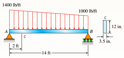
A simple beam with a rectangular cross section (width, 3,5 inL; height, 12 in,) carries a trapczoi-dally distributed load of 1400 lb/ft at A and 1000 lb/ft at B on a span of 14 ft (sec figure).

Find the principal stresses
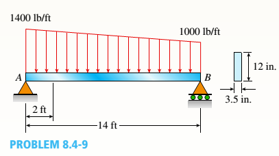
 2 and the maximum shear stress r__ at a cross section 2 ft from the left-hand support at each of the locations: (a) the neutral axis, (b) 2 in. above the neutral axis, and (c) the top of the beam. (Disregard the direct compressive stresses produced by the uniform load bearing against the top of the beam.)

  Chapter 8, Problem 8.4.9P, A simple beam with a rectangular cross section (width, 3,5 inL; height, 12 in,) carries a

(a).

Expert Solution
Check Mark
To determine

To find: Values of principal stress and maximum shear stress at neutral axis.

Answer to Problem 8.4.9P

Principal stress:

σ1=218.71 psi ,σ2=218.71 psi

Maximum shear stressτmax=218.71 psi

Explanation of Solution

Given Information:

Beam lengthL=14 ft=168 in

Dimensions of beam,

h=12 inb=3.5 in

Concept Used:

Bending stressσx=MyI

Shear stressτxy=VQIt

Principal normal stressesσ1,2=σx+σy2±(σxσy2)2+τxy2

Maximum shear stressτmax=(σxσy2)2+τxy2

Bundle: Mechanics Of Materials, Loose-leaf Version, 9th + Mindtap Engineering, 2 Terms (12 Months) Printed Access Card, Chapter 8, Problem 8.4.9P , additional homework tip  1

Load at pointC :

WC=1000+400×1214=1342.86 lb

From equilibrium;

RA×1412(1000+1400)×14×[143×1000+2×14001000+1400]=0RA=8866.67 lb

So, bending moment at pointC is :

  M=RA×212(1342.86+1400)×2×[23×1342.86+2×14001342.86+1400]M=14971.43 lb-ftM=179657.2 lb-in

Shear force atC is

  V=RA12(1342.86+1400)×2=6123.8 lb

Moment of inertia:

  I=bh312I=3.5×12312I=504 in4

First moment of area above neutral axis.:

  Q=A1×y1=3.5×6×(6/2)=63 in3

So, bending stress at neutral axis::

σx=M(y=0)Iσx=0 ksi

And shear stress at that point:

τxy=VQItτxy=6123.8×63504×3.5τxy=218.71 psi

For this situation no stress iny direction soσy=0

Values of principal and normal stress are given by following equation:

σ1,2=σx+σy2±(σxσy2)2+τxy2σ1,2=0+02±(002)2+218.712σ1,2=0±218.71σ1=0+218.71=218.71 psiσ2=0218.71=218.71 psi

Maximum shear stress:

τmax=(σxσy2)2+τxy2τmax=(002)2+218.712τmax=218.71 psi

Conclusion:

Hence, we get:

Principal stresses

σ1=218.71 psi ,σ2=218.71 psi

Maximum shear stressτmax=218.71 psi

(b).

Expert Solution
Check Mark
To determine

To find: Values of Principal stress and maximum shear stress at 2 in above neutral axis.

Answer to Problem 8.4.9P

Principal stress:

σ1=762.47 psi ,σ2=49.53 psi

Maximum shear stress:

  τmax=406.0 psi

Explanation of Solution

Given Information:

Beam lengthL=14 ft=168 in

Dimensions of beam,

h=12 inb=3.5 in

Concept Used:

Bending stressσx=MyI

Shear stressτxy=VQIt

Principal normal stressesσ1,2=σx+σy2±(σxσy2)2+τxy2

Maximum shear stressτmax=(σxσy2)2+τxy2

Bundle: Mechanics Of Materials, Loose-leaf Version, 9th + Mindtap Engineering, 2 Terms (12 Months) Printed Access Card, Chapter 8, Problem 8.4.9P , additional homework tip  2

Load at pointC :

WC=1000+400×1214=1342.86 lb

From equilibrium:

RA×1412(1000+1400)×14×[143×1000+2×14001000+1400]=0RA=8866.67 lb

So, bending moment at pointC is :

  M=RA×212(1342.86+1400)×2×[23×1342.86+2×14001342.86+1400]M=14971.43 lb-ftM=179657.2 lb-in

Shear force atC is

  V=RA12(1342.86+1400)×2=6123.8 lb

Moment of inertia:

  I=bh312I=3.5×12312I=504 in4

First moment of area above given point:

  Q=A1×y1=3.5×4×(2+2)=56 in3

So, bending stress at given point:

σx=MyIσx=179657.2×2504σx=712.93 psi

And shear stress at that point:

τxy=VQItτxy=6123.8×56504×3.5τxy=194.41 psi

For this situation no stress iny direction soσy=0

Values of principal and normal stress are given by following equation:

σ1,2=σx+σy2±(σxσy2)2+τxy2σ1,2=712.93+02±(712.9302)2+194.412σ1,2=356.47±406.0σ1=356.47+406.0=762.47 psiσ2=356.47406.0=49.53 psi

Maximum shear stress ::

τmax=(σxσy2)2+τxy2τmax=(712.9302)2+194.412τmax=406 psi

Conclusion:

Hence, we get;

Principal stresses

σ1=762.47 psi ,σ2=49.53 psi.

Maximum shear stressτmax=406.0 psi.

(c).

Expert Solution
Check Mark
To determine

To find: Values of principal stress and maximum shear stress at top of beam.

Answer to Problem 8.4.9P

Values of principal stress;

σ1=2138.8 psi ,σ2=0 psi

Maximum shear stressτmax=1069.4 psi

Explanation of Solution

Given Information:

Beam lengthL=14 ft=168 in

Dimensions of beam,

h=12 inb=3.5 in

Concept Used:

Bending stressσx=MyI

Shear stressτxy=VQIt

Values of principal stress are:σ1,2=σx+σy2±(σxσy2)2+τxy2

  1. Maximum shear stress:

  τmax=(σxσy2)2+τxy2

Bundle: Mechanics Of Materials, Loose-leaf Version, 9th + Mindtap Engineering, 2 Terms (12 Months) Printed Access Card, Chapter 8, Problem 8.4.9P , additional homework tip  3

Load at pointC :

WC=1000+400×1214=1342.86 lb

From equilibrium:

RA×1412(1000+1400)×14×[143×1000+2×14001000+1400]=0RA=8866.67 lb

So, bending moment at pointC is :

  M=RA×212(1342.86+1400)×2×[23×1342.86+2×14001342.86+1400]M=14971.43 lb-ftM=179657.2 lb-in

Moment of inertia:

  I=bh312I=3.5×12312I=504 in4

First moment of area at the top of beam shall be zero,Q=0 m3

So, bending stress at top::

σx=MyIσx=179657.2×6504σx=2138.8 psi

And shear stress at that point:

τ=VQItτ=0 ksi

For this situation no stress iny direction soσy=0

Values of principal and normal stress are given by following equation::

σ1,2=σx+σy2±(σxσy2)2+τxy2σ1,2=2138.8+02±(2138.802)2+02σ1,2=1069.4±1069.4σ1=1069.4+1069.4=2138.8 psiσ2=1069.41069.4=0 psi

Maximum shear stress:

τmax=(σxσy2)2+τxy2τmax=(2138.802)2+02τmax=1069.4 psi

Conclusion:

Hence, we get:

Values of principal stress:

σ1=2138.8 psi ,σ2=0 psi

Maximum shear stressτmax=1069.4 psi .

Want to see more full solutions like this?

Subscribe now to access step-by-step solutions to millions of textbook problems written by subject matter experts!
Students have asked these similar questions
Both portions of the rod ABC are made of an aluminum for which E = 70 GPa. Based on the given information find: 1- deformation at A 2- stress in BC 3- Total strain 4- If v (Poisson ratio is 0.25, find the lateral deformation of AB Last 3 student ID+ 300 mm=L2 724 A P=Last 2 student ID+ 300 KN 24 24 Diameter Last 2 student ID+ 15 mm Last 3 student ID+ 500 mm=L1 724 C B 24 Q=Last 2 student ID+ 100 KN 24 Diameter Last 2 student ID+ 40 mm
Q2Two wooden members of uniform cross section are joined by the simple scarf splice shown. Knowing that the maximum allowable tensile stress in the glued splice is 75 psi, determine (a) the largest load P that can be safely supported, (b) the corresponding shearing stress in the splice. น Last 1 student ID+5 inch=W =9 4 L=Last 1 student ID+8 inch =12 60° P'
Q4 The two solid shafts are connected by gears as shown and are made of a steel for which the allowable shearing stress is 7000 psi. Knowing the diameters of the two shafts are, respectively, dBC determine the largest torque Tc that can be applied at C. 4 and dEF dBC=Last 1 student ID+3 inch dEF=Last 1 student ID+1 inch 7 R=Last 1 Student ID+5 inch 9 R B Tc 2.5 in. E TF H

Chapter 8 Solutions

Bundle: Mechanics Of Materials, Loose-leaf Version, 9th + Mindtap Engineering, 2 Terms (12 Months) Printed Access Card

Ch. 8 - A spherical stainless-steel tank having a diameter...Ch. 8 - Solve the preceding problem if the diameter is 480...Ch. 8 - : A hollow, pressurized sphere having a radius r =...Ch. 8 - A fire extinguisher tank is designed for an...Ch. 8 - Prob. 8.3.2PCh. 8 - A scuba t a n k (see fig ure) i s bci ng d e...Ch. 8 - A tall standpipc with an open top (see figure) has...Ch. 8 - An inflatable structure used by a traveling circus...Ch. 8 - A thin-walled cylindrical pressure vessel of a...Ch. 8 - A strain gage is installed in the longitudinal...Ch. 8 - A circular cylindrical steel tank (see figure)...Ch. 8 - A cylinder filled with oil is under pressure from...Ch. 8 - Solve the preceding problem if F =90 mm, F = 42...Ch. 8 - A standpipe in a water-supply system (see figure)...Ch. 8 - A cylindrical tank with hemispherical heads is...Ch. 8 - : A cylindrical tank with diameter d = 18 in, is...Ch. 8 - A pressurized steel tank is constructed with a...Ch. 8 - Solve the preceding problem for a welded Tank with...Ch. 8 - A wood beam with a cross section 4 x 6 in. is...Ch. 8 - Prob. 8.4.2PCh. 8 - A simply supported beam is subjected to two point...Ch. 8 - A cantilever beam with a width h = 100 mm and...Ch. 8 - A beam with a width h = 6 in. and depth h = 8 in....Ch. 8 - Beam ABC with an overhang BC is subjected to a...Ch. 8 - A cantilever beam(Z, = 6 ft) with a rectangular...Ch. 8 - Solve the preceding problem for the following...Ch. 8 - A simple beam with a rectangular cross section...Ch. 8 - An overhanging beam ABC has a guided support at A,...Ch. 8 - Solve the preceding problem if the stress and...Ch. 8 - A cantilever wood beam with a width b = 100 mm and...Ch. 8 - . A cantilever beam (width b = 3 in. and depth h =...Ch. 8 - A beam with a wide-flange cross section (see...Ch. 8 - A beam with a wide-flange cross section (see...Ch. 8 - A W 200 x 41.7 wide-flange beam (see Table F-l(b),...Ch. 8 - A W 12 x 35 steel beam is fixed at A. The beam has...Ch. 8 - A W 360 x 79 steel beam is fixed at A. The beam...Ch. 8 - A W 12 X 14 wide-flange beam (see Table F-l(a),...Ch. 8 - A cantilever beam with a T-section is loaded by an...Ch. 8 - Beam A BCD has a sliding support at A, roller...Ch. 8 - , Solve the preceding problem using the numerical...Ch. 8 - A W 12 x 35 steel cantilever beam is subjected to...Ch. 8 - A W 310 x 52 steel beam is subjected to a point...Ch. 8 - A solid circular bar is fixed at point A. The bar...Ch. 8 - A cantilever beam with a width h = 100 mm and...Ch. 8 - Solve the preceding problem using the following...Ch. 8 - A cylindrical tank subjected to internal...Ch. 8 - A cylindrical pressure vessel having a radius r =...Ch. 8 - A pressurized cylindrical tank with flat ends is...Ch. 8 - A cylindrical pressure vessel with flat ends is...Ch. 8 - The tensional pendulum shown in the figure...Ch. 8 - The hollow drill pipe for an oil well (sec figure)...Ch. 8 - Solve the preceding problem if the diameter is 480...Ch. 8 - . A segment of a generator shaft with a hollow...Ch. 8 - A post having a hollow, circular cross section...Ch. 8 - A sign is supported by a pole of hollow circular...Ch. 8 - A sign is supported by a pipe (see figure) having...Ch. 8 - A traffic light and signal pole is subjected to...Ch. 8 - Repeat the preceding problem but now find the...Ch. 8 - A bracket ABCD having a hollow circular cross...Ch. 8 - A gondola on a ski lift is supported by two bent...Ch. 8 - Beam A BCD has a sliding support at A, roller...Ch. 8 - A double-decker bicycle rack made up of square...Ch. 8 - A semicircular bar AB lying in a horizontal plane...Ch. 8 - Repeat Problem 8.5-22 but replace the square tube...Ch. 8 - An L-shaped bracket lying in a horizontal plane...Ch. 8 - A horizontal bracket ABC consists of two...Ch. 8 - , An arm A BC lying in a horizontal plane and...Ch. 8 - A crank arm consists of a solid segment of length...Ch. 8 - A moveable steel stand supports an automobile...Ch. 8 - A mountain bike rider going uphill applies a force...Ch. 8 - Determine the maximum tensile, compressive, and...Ch. 8 - Prob. 8.5.32PCh. 8 - A plumber's valve wrench is used to replace valves...Ch. 8 - A compound beam ABCD has a cable with force P...Ch. 8 - A steel hanger bracket ABCD has a solid, circular...
Knowledge Booster
Background pattern image
Mechanical Engineering
Learn more about
Need a deep-dive on the concept behind this application? Look no further. Learn more about this topic, mechanical-engineering and related others by exploring similar questions and additional content below.
Similar questions
SEE MORE QUESTIONS
Recommended textbooks for you
Text book image
Mechanics of Materials (MindTap Course List)
Mechanical Engineering
ISBN:9781337093347
Author:Barry J. Goodno, James M. Gere
Publisher:Cengage Learning
Mechanics of Materials Lecture: Beam Design; Author: UWMC Engineering;https://www.youtube.com/watch?v=-wVs5pvQPm4;License: Standard Youtube License