
Find the vertical stress increase at 4 m below A, B, and C.
Answer to Problem 8.27CTP
The increase in the vertical stress
The increase in the vertical stress
The increase in the vertical stress
Explanation of Solution
Given information:
The depth of the point from the ground level,
The intensity of the uniform pressure,
Calculation:
Vertical stress increase at point A:
Show the free-body diagram of the L-shaped raft as in Figure 1.
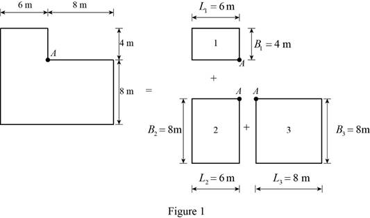
Rectangle 1:
Find the value of
Substitute 4 m for
Find the value of
Substitute 6 m for
Refer Figure 8.16 “Variation of
For
The value of variation
Find the increase in vertical stress
Substitute
Rectangle 2:
Find the value of
Substitute 8 m for
Find the value of
Substitute 6 m for
Refer Figure 8.16 “Variation of
For
The value of variation
Find the increase in vertical stress
Substitute
Rectangle 3:
Find the value of
Substitute 8 m for
Find the value of
Substitute 8 m for
Refer Figure 8.16 “Variation of
For
The value of variation
Find the increase in vertical stress
Substitute
Find the increase in vertical stress
Substitute
Therefore, the increase in the vertical stress
The vertical stress increase at point B:
Show the free-body diagram of the L-shaped raft as in Figure 2.
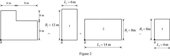
Rectangle 1:
Find the value of
Substitute 12 m for
Find the value of
Substitute 6 m for
Refer Figure 8.16 “Variation of
For
The value of variation
Find the increase in vertical stress
Substitute
Rectangle 2:
Find the value of
Substitute 8 m for
Find the value of
Substitute 14 m for
Refer Figure 8.16 “Variation of
For
The value of variation
Find the increase in vertical stress
Substitute
Rectangle 3:
Find the value of
Substitute 8 m for
Find the value of
Substitute 6 m for
Refer Figure 8.16 “Variation of
For
The value of variation
Find the increase in vertical stress
Substitute
Find the increase in vertical stress
Substitute
Therefore, the increase in the vertical stress
The vertical stress increase at point C:
Show the free-body diagram of the L-shaped raft as in Figure 3.
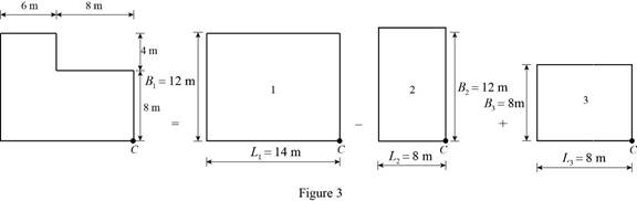
Rectangle 1:
Find the value of
Substitute 12 m for
Find the value of
Substitute 14 m for
Refer Figure 8.16 “Variation of
For
The value of variation
Find the increase in vertical stress
Substitute
Rectangle 2:
Find the value of
Substitute 12 m for
Find the value of
Substitute 8 m for
Refer Figure 8.16 “Variation of
For
The value of variation
Find the increase in vertical stress
Substitute
Rectangle 3:
Find the value of
Substitute 8 m for
Find the value of
Substitute 8 m for
Refer Figure 8.16 “Variation of
For
The value of variation
Find the increase in vertical stress
Substitute
Find the increase in vertical stress
Substitute
Therefore, the increase in the vertical stress
Want to see more full solutions like this?
Chapter 8 Solutions
Fundamentals of Geotechnical Engineering (MindTap Course List)

- A4.3- Design a square short column for P₁ = 1800 kN, Mfx = 250 kN.m, Mfy: f your final design p has to be between 0.01 and 0.02. = 50 kN.m. In Given: f'c = 25 MPa fy = 400 MPa Longitudinal bars: Use 25M Ties: 10M@ 300 Clear cover to the ties: 40mmarrow_forwardA4.1- For a concentrically loaded tied short column, with the cross-section shown in Figure 1, a) Find the axial load resistance of the column; b) Check if the spacing between the longitudinal bars is satisfying code requirements; c) Determine the required spacing between the ties, and sketch the tie arrangement as per the code. Given: f'c = 25 MPa fy = 400 MPa T 550 mm 550 mm Maximum aggregate size: 20mm Longitudinal bars: 8-25M Figure 1 Ties: 10M (ties are not shown on cross-section. The arrangement to be determined in part c) Clear cover to the ties: 40mmarrow_forwardWhen using a work breakdown structure (WBS) for a project why it is necessary to break down activities?arrow_forward
- As shown in the figure below, a 1.5 m × 1.5 m footing is carrying a 400 kN load. P Depth (m) 0.0 1.0 2.0 Df Groundwater table (Yw = 9.81 kN/m³) 3.5 Yt = 16.5 kN/m³ E = 9,000 kPa Sandy soil Ysat 17.5 kN/m³ E = 15,000 kPa 6.0 Stiff Clay (OCR = 2) Bedrock Ysat 18.0 kN/m³ eo = 0.8 Cc = 0.15, Cr = 0.02 Eu =40,000 kPa (a) Estimate the immediate settlement beneath the center of the footing. Assuming that Poisson's ratios of sand and soft clay are 0.3 and 0.5, respectively. Use numerical integration approach. For the calculations, use layers (below the bottom of the footing) of thicknesses: 1 m; 1.5 m, and 2.5 m. (b) Determine the primary consolidation settlement beneath the center of the footing. (c) Redo Part (b) if OCR=1.1. Note: Use the 2:1 method to determine the stress increase below the footing. For parts (b) and (c), use the one-dimensional consolidation theory.arrow_forwardConsider the cross-sections illustrated in the next slides. Implement a cross-sectional analysis based on a layered discretisation of the cross- section as required at the following. 1) Develop the implementation of an analysis to estimate the nonlinear response of the composite steel-concrete section, of the reinforced concrete section and of the steel section shown in following slides (using material nonlinear models provided in the support files). Provide the details of the numerical implementation with clear explanations of all steps. Hint: the implementation can be done in Excel. 2) Discuss how the 3 cross-sections (shown in the next slides) compare to each other in terms of embodied carbon under the condition that the cross-sections possess the same nominal moment capacity (i.e. the peak moment achieved in the moment-curvature diagram). The discussion should include at least 2 sets of the sections (each set contains one composite section, one reinforced concrete section and one…arrow_forwardConsider the following static route choice problem where 110 vehicles travel from point A to point B. The corresponding travel time (in minutes) of each link is as follows: t₁ = x1; t₂ = x2 + 20; t3x3 + 10; t₁ = 3×4 where Xi denotes the number of vehicles that choose link i. Find the number of vehicles that travel on each link when a. The user equilibrium condition (UE) is satisfied, where vehicles select the route with the minimum travel time; and b. The system optimum condition (SO) is satisfied, where the total travel time is minimised. C. Report the total delay savings when satisfying SO instead of UE. 2 B A 3 4arrow_forward
- = α₂+ Assume an origin is connected to a destination with two routes. Assume the travel time of each route has a linear relationship with the traffic flow on the route (t₁ = α₁ + b₁x₁ ; t₂ b2x2). Determine under what condition (e.g. a relationship among the parameters of the performance functions) tolling cannot reduce the total travel time of the two routes.arrow_forwardBeban berjalan pada konstruksi balok seperti pada gambar, tentukan besar gaya dalam yang terjadi dengan metode Garis Pengaruh. Gaya dalam berupa : Reaksi tumpuan RA dan RB, Gaya lintang max di titik C, Momen Maksimum di titik C A + Dimana: B D 10 5 m 5 m P1 = 12t P2 = 6t P3 = 18t q= 6 t/m 2 3 q = 6 t/m P1 P2 P3arrow_forwardConsider the following static route choice problem where 110 vehicles travel from point A to point B. The corresponding travel time (in minutes) of each link is as follows: t₁ = x1 ; t₂ = = x2 + 20; t3 = x3 + 10; t₁ = 3x4 where Xi denotes the number of vehicles that choose link i. Find the number of vehicles that travel on each link when a. The user equilibrium condition (UE) is satisfied, where vehicles select the route with the minimum travel time; and b. The system optimum condition (SO) is satisfied, where the total travel time is minimised. C. Report the total delay savings when satisfying SO instead of UE. 2 A B 3 4arrow_forward
- = Assume an origin is connected to a destination with two routes. Assume the travel time of each route has a linear relationship with the traffic flow on the route (t₁ = α₁ + b₁×₁ ; t₂ b2x2). Determine under what condition (e.g. a relationship among the parameters of the performance functions) tolling cannot reduce the total travel time of the two routes. a2+arrow_forwardFor the soil system presented below, calculate and draw diagrams of distributions of the totaland effective stresses and pore water pressure. Assume an upward water flow with a velocity of0.000,001 cm/s.arrow_forwardRefer to attached problem.arrow_forward
 Fundamentals of Geotechnical Engineering (MindTap...Civil EngineeringISBN:9781305635180Author:Braja M. Das, Nagaratnam SivakuganPublisher:Cengage Learning
 Principles of Foundation Engineering (MindTap Cou...Civil EngineeringISBN:9781337705028Author:Braja M. Das, Nagaratnam SivakuganPublisher:Cengage Learning
 Principles of Geotechnical Engineering (MindTap C...Civil EngineeringISBN:9781305970939Author:Braja M. Das, Khaled SobhanPublisher:Cengage Learning
 Principles of Foundation Engineering (MindTap Cou...Civil EngineeringISBN:9781305081550Author:Braja M. DasPublisher:Cengage Learning