Fundamentals of Geotechnical Engineering (MindTap Course List)
5th Edition
ISBN: 9781305635180
Author: Braja M. Das, Nagaratnam Sivakugan
Publisher: Cengage Learning
expand_more
expand_more
format_list_bulleted
Concept explainers
Textbook Question
Chapter 8, Problem 8.19P
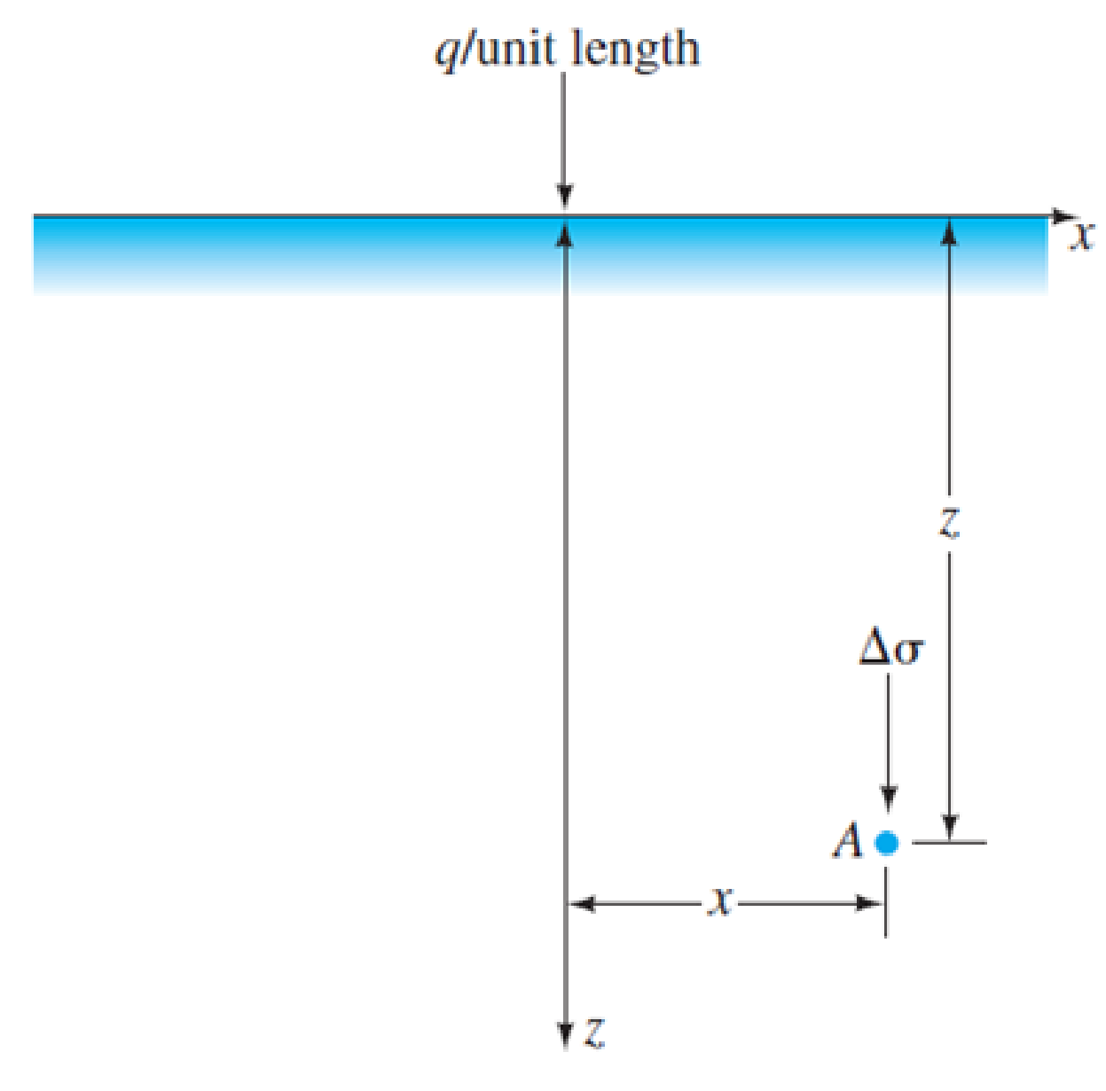
Refer to Figure 8.13. The magnitude of the line load q is 45 kN/m. Calculate and plot the variation of the vertical stress increase, Δσ between the limits of x = −10 m and x = +10 m, given z = 4 m.

FIG. 8.13 Line load over the surface of a semiinfinite soil mass
Expert Solution & Answer
Trending nowThis is a popular solution!

Students have asked these similar questions
What is Highway engineering
Determine the vertical displacement of joint A. Each bar is made of steel and has the cross-sectional area shown. Take E = 29,000 ksi. Use the method of virtual work.
Sketch the Energy Line and the Hydraulic Grade Line through the Venturi meter. Label the contribution of each term from bernoulli equation
Chapter 8 Solutions
Fundamentals of Geotechnical Engineering (MindTap Course List)
Ch. 8 - Prob. 8.1PCh. 8 - Prob. 8.2PCh. 8 - Prob. 8.3PCh. 8 - Prob. 8.4PCh. 8 - Prob. 8.5PCh. 8 - Prob. 8.6PCh. 8 - Prob. 8.7PCh. 8 - Prob. 8.8PCh. 8 - Prob. 8.9PCh. 8 - The soil profile at a site consists of 10 m of...
Ch. 8 - Prob. 8.11PCh. 8 - Prob. 8.12PCh. 8 - Prob. 8.13PCh. 8 - Prob. 8.14PCh. 8 - A sand has Gs = 2.66. Calculate the hydraulic...Ch. 8 - Prob. 8.16PCh. 8 - A point load of 1000 kN is applied at the ground...Ch. 8 - Point loads of magnitude 9, 18, and 27 kN act at...Ch. 8 - Refer to Figure 8.13. The magnitude of the line...Ch. 8 - Refer to Figure 8.24. Determine the vertical...Ch. 8 - Consider a circularly loaded flexible area on the...Ch. 8 - A flexible circular footing of radius R carries a...Ch. 8 - The plan of a flexible rectangular loaded area is...Ch. 8 - Refer to Figure 8.26. The circular flexible area...Ch. 8 - Refer to Figure 8.27. The flexible area is...Ch. 8 - Prob. 8.26CTPCh. 8 - Prob. 8.27CTP
Knowledge Booster
Learn more about
Need a deep-dive on the concept behind this application? Look no further. Learn more about this topic, civil-engineering and related others by exploring similar questions and additional content below.Similar questions
- 2. Design a storage and distribution system for the town of Waffle. The requirements are that fire protection shall be provided, the minimum water pressure at the top of the apartments is to be 240 kPa and the maximum system pressure is to be 550 kPa. The following assumptions may be used: Each of the four apartment buildings is occupied by 50 residents. Each apartment building is four stories high. Each story is 3 meters high. Each house is occupied by three residents. Average daily demand for the village is 500 Lpcd and the peak hourly demand factor is 6.2. Needed fire flow for the houses is 230 m3/h. and for apartment building is 500 m3/h, with 2 h duration. System pressure is to be provided from the elevated storage tank. Minor pressure losses in buildings may be ignored. The distribution system will not contain any loops. Assume that emergency supply (ES), fire department supply (FDS) or off peak pumping are not provided (they are all equal to zero). Provide the following…arrow_forward1. The city of Ten Sleep proposes to use Crater Lake for its water supply. Water quality analysis results revealed no detectable Giardia, viruses, or Cryptosporidium in the source water (Giardia cysts <1/100 L; Viruses <1/100 L; Cryptosporidium oocysts <0.075/L). Design a disinfection system to treat 3,500 m³/d by direct filtration and chlorine dioxide (CIO2) will be used as a primary disinfectant. The filtered water has a pH of 7.5 and a temperature of 5°C. Provide the following information for your design: • Determine the total removal/inactivation required for disinfection for each pathogen group • Determine the required CT value to achieve the required inactivation for the design conditions (pH, temperature)arrow_forwardFor the beam shown, where is the peak value of the bending moment diagram? P a. Above C b. Below B c. Above A d. Above B Barrow_forward
- The plane truss shown is a. statically indeterminate b. unstable c. statically determinatearrow_forwardA simple supported one-way slab spans 24 ft. In addition to its own weight, it supports an uniformly distributed service live load of 100 psf. A masonry wall, which has a service dead load of 1500 lb/ft, is also supported by the slab along with an uniform service floor live load (a line load) of 500 lb/ft loaded as shown below in the figure. (a) (b) Select the depth of the slab using ACI Code's minimum thickness requirements where deflections are not computed. Design the primary steel and temperature steel and show your results in a sketch. The concrete is light-weight concrete and has a unit weight of 110 lb/ft³. Assume 3/4 inch cover on the reinforcement aand that f' 3 ksi and f₁ = 60 ksi. Use #6 bars for the primary steel and #4 bars for the shrinkage and temperature steel. Assume interior exposure, and use ACI 318-19. Repeat part (a) NOT using the ACI Code's minimum thickness requirements for cases where deflections are not computed. Use #6 bars for the primary steel and #4 bars…arrow_forwardWater (at 10° C has n = 1.31 x 10⁶ m²/s) flows from reservoir A (surface elevation 100 m) through a 2.25-m-diameter concrete pipe (e = 0.36 mm; f=0.014) to reservoir B (surface elevation 91.84 m). If the 2 reservoirs are 17 km apart, find the flow velocity V (to 2 decimal places x.xx) ignoring minor losses. 100 m A L = 17 km P₁ h₁ + = + V² 2g D=2.25 m 91.84 m B + h₂ 2g P₂ = =h₂+ + Varrow_forward
- The floor system of an apartment building consists of a 4-inch-thick reinforced concrete slab resting on three steel floor beams, which are in turn supported by two steel girders, as shown below. The areas of cross section of the floor beams and the girders are 18.3 in.2 and 32.7 in.², respectively. Determine the dead load acting on the beam CD. Steel girder (A-32.7 in.2) At I- 25 ft B I Steel column C D Steel floor beam (A =18.3 in.2) I a. 600.0 lb/ft b. 662.3 lb/ft c. 62.3 lb/ft d. 1347.3 lb/ft E 4 in. concrete slab 2 at 12 ft = 24 ftarrow_forwardWhat is the classification of the structure shown below? Hinge a. Internally unstable, statically indeterminate b. Internally stable, statically determinate c. Internally stable, statically indeterminate Od. Internally unstable, statically determinatearrow_forwardship construction question. Sketch a bilge keel, garboard strake and sheer strake.arrow_forward
arrow_back_ios
SEE MORE QUESTIONS
arrow_forward_ios
Recommended textbooks for you
 Principles of Geotechnical Engineering (MindTap C...Civil EngineeringISBN:9781305970939Author:Braja M. Das, Khaled SobhanPublisher:Cengage Learning
 Fundamentals of Geotechnical Engineering (MindTap...Civil EngineeringISBN:9781305635180Author:Braja M. Das, Nagaratnam SivakuganPublisher:Cengage Learning
 Principles of Foundation Engineering (MindTap Cou...Civil EngineeringISBN:9781337705028Author:Braja M. Das, Nagaratnam SivakuganPublisher:Cengage Learning
 Principles of Foundation Engineering (MindTap Cou...Civil EngineeringISBN:9781305081550Author:Braja M. DasPublisher:Cengage Learning

Principles of Geotechnical Engineering (MindTap C...
Civil Engineering
ISBN:9781305970939
Author:Braja M. Das, Khaled Sobhan
Publisher:Cengage Learning

Fundamentals of Geotechnical Engineering (MindTap...
Civil Engineering
ISBN:9781305635180
Author:Braja M. Das, Nagaratnam Sivakugan
Publisher:Cengage Learning

Principles of Foundation Engineering (MindTap Cou...
Civil Engineering
ISBN:9781337705028
Author:Braja M. Das, Nagaratnam Sivakugan
Publisher:Cengage Learning

Principles of Foundation Engineering (MindTap Cou...
Civil Engineering
ISBN:9781305081550
Author:Braja M. Das
Publisher:Cengage Learning
Stress Distribution in Soils GATE 2019 Civil | Boussinesq, Westergaard Theory; Author: Gradeup- GATE, ESE, PSUs Exam Preparation;https://www.youtube.com/watch?v=6e7yIx2VxI0;License: Standard YouTube License, CC-BY