Vector Mechanics for Engineers: Statics and Dynamics
12th Edition
ISBN: 9781259638091
Author: Ferdinand P. Beer, E. Russell Johnston Jr., David Mazurek, Phillip J. Cornwell, Brian Self
Publisher: McGraw-Hill Education
expand_more
expand_more
format_list_bulleted
Textbook Question
Chapter 8, Problem 8.138RP
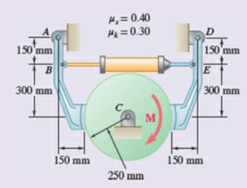
The hydraulic cylinder shown exerts a force of 3 kN directed to the right on point B and to the left on point E. Determine the magnitude of the couple M required to rotate the drum clockwise at a constant speed.

Fig. P8.138
Expert Solution & Answer
Want to see the full answer?
Check out a sample textbook solution
Students have asked these similar questions
Can you solve it analytically using laplace transforms and with Matlab code as well please. Thank You
Can you solve it analytically using laplace transforms and with Matlab code as well please. Thank You.
Q11. Determine the magnitude of the reaction force at C.
1.5 m
a)
4 KN
D
b)
6.5 kN
c)
8 kN
d)
e)
11.3 KN
20 kN
-1.5 m-
C
4 kN
-1.5 m
B
Mechanical engineering, No
Chatgpt.
Chapter 8 Solutions
Vector Mechanics for Engineers: Statics and Dynamics
Ch. 8.1 - Knowing that the coefficient of friction between...Ch. 8.1 - Two blocks A and B are connected by a cable as...Ch. 8.1 - A cord is attached to and partially wound around a...Ch. 8.1 - A 40-kg packing crate must be moved to the left...Ch. 8.1 - Determine whether the block shown is in...Ch. 8.1 - Determine whether the block shown is in...Ch. 8.1 - Determine whether the block shown is in...Ch. 8.1 - Determine whether the block shown is in...Ch. 8.1 - Knowing that = 45 in Prob. 8.1, determine the...Ch. 8.1 - The 20-lb block A hangs from a cable as shown....
Ch. 8.1 - The 10-kg block is attached to link AB and rests...Ch. 8.1 - Considering only values of less than 90,...Ch. 8.1 - Prob. 8.9PCh. 8.1 - Prob. 8.10PCh. 8.1 - The 50-lb block A and the 25-lb block B are...Ch. 8.1 - The 50-lb block A and the 25-lb block B are...Ch. 8.1 - Three 4-kg packages A, B, and C are placed on a...Ch. 8.1 - Prob. 8.14PCh. 8.1 - A uniform crate with a mass of 30 kg must be moved...Ch. 8.1 - A worker slowly moves a 50-kg crate to the left...Ch. 8.1 - Prob. 8.17PCh. 8.1 - A 200-lb sliding door is mounted on a horizontal...Ch. 8.1 - Prob. 8.19PCh. 8.1 - Prob. 8.20PCh. 8.1 - Prob. 8.21PCh. 8.1 - Prob. 8.22PCh. 8.1 - The 10-lb uniform rod AB is held in the position...Ch. 8.1 - Prob. 8.24PCh. 8.1 - Prob. 8.25PCh. 8.1 - Prob. 8.26PCh. 8.1 - The press shown is used to emboss a small seal at...Ch. 8.1 - The machine base shown has a mass of 75 kg and is...Ch. 8.1 - Prob. 8.29PCh. 8.1 - Prob. 8.30PCh. 8.1 - Prob. 8.31PCh. 8.1 - Prob. 8.32PCh. 8.1 - Prob. 8.33PCh. 8.1 - A driver starts the engine of an automobile that...Ch. 8.1 - Prob. 8.35PCh. 8.1 - Two uniform rods each of weight W and length L are...Ch. 8.1 - A 1.2-m plank with a mass of 3 kg rests on two...Ch. 8.1 - Two identical uniform boards, each with a weight...Ch. 8.1 - A uniform 20-kg tube resting on a loading dock...Ch. 8.1 - Prob. 8.40PCh. 8.1 - A 10-ft beam, weighing 1200 lb, is to be moved to...Ch. 8.1 - (a) Show that the beam of Prob. 8.41 cannot be...Ch. 8.1 - Two 8-kg blocks A and B resting on shelves are...Ch. 8.1 - Prob. 8.44PCh. 8.1 - Prob. 8.45PCh. 8.1 - Two slender rods of negligible weight are...Ch. 8.1 - Two slender rods of negligible weight are...Ch. 8.2 - The machine part ABC is supported by a...Ch. 8.2 - Prob. 8.49PCh. 8.2 - Prob. 8.50PCh. 8.2 - Prob. 8.51PCh. 8.2 - Prob. 8.52PCh. 8.2 - Solve Prob. 8.52 assuming that the end of the beam...Ch. 8.2 - Prob. 8.54PCh. 8.2 - Prob. 8.55PCh. 8.2 - Block A supports a pipe column and rests as shown...Ch. 8.2 - A 200-lb block rests as shown on a wedge of...Ch. 8.2 - Prob. 8.58PCh. 8.2 - Prob. 8.59PCh. 8.2 - Prob. 8.60PCh. 8.2 - Prob. 8.61PCh. 8.2 - An 8 wedge is to be forced under a machine base at...Ch. 8.2 - Prob. 8.63PCh. 8.2 - A 15 wedge is forced under a 50-kg pipe as shown....Ch. 8.2 - A 15 wedge is forced under a 50-kg pipe as shown....Ch. 8.2 - Prob. 8.66PCh. 8.2 - Prob. 8.67PCh. 8.2 - Prob. 8.68PCh. 8.2 - Prob. 8.69PCh. 8.2 - Prob. 8.70PCh. 8.2 - Prob. 8.71PCh. 8.2 - The position of the automobile jack shown is...Ch. 8.2 - Prob. 8.73PCh. 8.2 - Prob. 8.74PCh. 8.2 - In the vise shown, the screw is single-threaded in...Ch. 8.2 - Prob. 8.76PCh. 8.3 - A lever of negligible weight is loosely fitted...Ch. 8.3 - Prob. 8.78PCh. 8.3 - 8.79 and 8.80 The double pulley shown is attached...Ch. 8.3 - Prob. 8.80PCh. 8.3 - 8.81 and 8.82 The double pulley shown is attached...Ch. 8.3 - Prob. 8.82PCh. 8.3 - Prob. 8.83PCh. 8.3 - The block and tackle shown are used to lower a...Ch. 8.3 - Prob. 8.85PCh. 8.3 - Prob. 8.86PCh. 8.3 - Prob. 8.87PCh. 8.3 - 8.87 and 8.88 A lever AB of negligible weight is...Ch. 8.3 - Prob. 8.89PCh. 8.3 - Prob. 8.90PCh. 8.3 - Prob. 8.91PCh. 8.3 - Prob. 8.92PCh. 8.3 - Prob. 8.93PCh. 8.3 - Prob. 8.94PCh. 8.3 - Prob. 8.95PCh. 8.3 - Prob. 8.96PCh. 8.3 - Solve Prob. 8.93 assuming that the normal force...Ch. 8.3 - Prob. 8.98PCh. 8.3 - Prob. 8.99PCh. 8.3 - A 900-kg machine base is rolled along a concrete...Ch. 8.3 - Prob. 8.101PCh. 8.3 - Prob. 8.102PCh. 8.4 - A rope having a weight per unit length of 0.4...Ch. 8.4 - A hawser is wrapped two full turns around a...Ch. 8.4 - Two cylinders are connected by a rope that passes...Ch. 8.4 - Prob. 8.106PCh. 8.4 - The coefficient of static friction between block B...Ch. 8.4 - Prob. 8.108PCh. 8.4 - A band belt is used to control the speed of a...Ch. 8.4 - Prob. 8.110PCh. 8.4 - The setup shown is used to measure the output of a...Ch. 8.4 - A flat belt is used to transmit a couple from drum...Ch. 8.4 - Prob. 8.113PCh. 8.4 - Prob. 8.114PCh. 8.4 - The speed of the brake drum shown is controlled by...Ch. 8.4 - The speed of the brake drum shown is controlled by...Ch. 8.4 - Prob. 8.117PCh. 8.4 - Bucket A and block C are connected by a cable that...Ch. 8.4 - Prob. 8.119PCh. 8.4 - Prob. 8.120PCh. 8.4 - 8.121 and 8.123 A cable is placed around three...Ch. 8.4 - Prob. 8.122PCh. 8.4 - Prob. 8.123PCh. 8.4 - Prob. 8.124PCh. 8.4 - Prob. 8.125PCh. 8.4 - Prob. 8.126PCh. 8.4 - The axle of the pulley is frozen and cannot rotate...Ch. 8.4 - The 10-lb bar AE is suspended by a cable that...Ch. 8.4 - Prob. 8.129PCh. 8.4 - Prove that Eqs. (8.13) and (8.14) are valid for...Ch. 8.4 - Complete the derivation of Eq. (8.15), which...Ch. 8.4 - Prob. 8.132PCh. 8.4 - Solve Prob. 8.113 assuming that the flat belt and...Ch. 8 - 8.134 and 8.135 The coefficients of friction are S...Ch. 8 - Prob. 8.135RPCh. 8 - Prob. 8.136RPCh. 8 - A slender rod with a length of L is lodged between...Ch. 8 - The hydraulic cylinder shown exerts a force of 3...Ch. 8 - Prob. 8.139RPCh. 8 - Bar AB is attached to collars that can slide on...Ch. 8 - Two 10 wedges of negligible weight are used to...Ch. 8 - A 10 wedge is used to split a section of a log....Ch. 8 - Prob. 8.143RPCh. 8 - A lever of negligible weight is loosely fitted...Ch. 8 - In the pivoted motor mount shown, the weight W of...
Knowledge Booster
Learn more about
Need a deep-dive on the concept behind this application? Look no further. Learn more about this topic, mechanical-engineering and related others by exploring similar questions and additional content below.Similar questions
- aversity of Baoyion aculty of Engineering-AIMusyab Automobile Eng. Dep. Year: 2022-2023, st Course, 1st Attempt Stage: 3rd Subject: Heat Transfer I Date: 2023\01\23- Monday Time: 3 Hours Q4: A thick slab of copper initially at a uniform temperature of 20°C is suddenly exposed to radiation at one surface such that the net heat flux is maintained at a constant value of 3×10⁵ W/m². Using the explicit finite-difference techniques with a space increment of Ax = = 75 mm, determine the temperature at the irradiated surface and at an interior point that is 150 mm from the surface after 2 min have elapsed. Q5: (12.5 M) A) A steel bar 2.5 cm square and 7.5 cm long is initially at a temperature of 250°C. It is immersed in a tank of oil maintained at 30°C. The heat-transfer coefficient is 570 W/m². C. Calculate the temperature in the center of the bar after 3 min. B) Air at 90°C and atmospheric pressure flows over a horizontal flat plate at 60 m/s. The plate is 60 cm square and is maintained at a…arrow_forwardUniversity of Baby on Faculty of Engineering-AIMusyab Automobile Eng. Dep. Year: 2022-2023. 1 Course, 1" Attempt Stage 3 Subject Heat Transfer I Date: 2023 01 23- Monday Time: 3 Hours Notes: Q1: • • Answer four questions only Use Troles and Appendices A) A flat wall is exposed to an environmental temperature of 38°C. The wall is covered with a layer of insulation 2.5 cm thick whose thermal conductivity is 1.4 W/m. C, and the temperature of the wall on the inside of the insulation is 315°C. The wall loses heat to the environment by convection. Compute the value of the convection heat-transfer coefficient that must be maintained on the outer surface of the insulation to ensure that the outer-surface temperature does not exceed 41°C. B) A vertical square plate, 30 cm on a side, is maintained at 50°C and exposed to room air at 20°C. The surface emissivity is 0.8. Calculate the total heat lost by both sides of the plate. (12.5 M) Q2: An aluminum fin 1.5 mm thick is placed on a circular tube…arrow_forwardSolve using graphical method and analytical method, only expert should solvearrow_forward
arrow_back_ios
SEE MORE QUESTIONS
arrow_forward_ios
Recommended textbooks for you
 Elements Of ElectromagneticsMechanical EngineeringISBN:9780190698614Author:Sadiku, Matthew N. O.Publisher:Oxford University Press
 Mechanics of Materials (10th Edition)Mechanical EngineeringISBN:9780134319650Author:Russell C. HibbelerPublisher:PEARSON
 Thermodynamics: An Engineering ApproachMechanical EngineeringISBN:9781259822674Author:Yunus A. Cengel Dr., Michael A. BolesPublisher:McGraw-Hill Education
 Control Systems EngineeringMechanical EngineeringISBN:9781118170519Author:Norman S. NisePublisher:WILEY
 Mechanics of Materials (MindTap Course List)Mechanical EngineeringISBN:9781337093347Author:Barry J. Goodno, James M. GerePublisher:Cengage Learning
 Engineering Mechanics: StaticsMechanical EngineeringISBN:9781118807330Author:James L. Meriam, L. G. Kraige, J. N. BoltonPublisher:WILEY

Elements Of Electromagnetics
Mechanical Engineering
ISBN:9780190698614
Author:Sadiku, Matthew N. O.
Publisher:Oxford University Press

Mechanics of Materials (10th Edition)
Mechanical Engineering
ISBN:9780134319650
Author:Russell C. Hibbeler
Publisher:PEARSON

Thermodynamics: An Engineering Approach
Mechanical Engineering
ISBN:9781259822674
Author:Yunus A. Cengel Dr., Michael A. Boles
Publisher:McGraw-Hill Education

Control Systems Engineering
Mechanical Engineering
ISBN:9781118170519
Author:Norman S. Nise
Publisher:WILEY

Mechanics of Materials (MindTap Course List)
Mechanical Engineering
ISBN:9781337093347
Author:Barry J. Goodno, James M. Gere
Publisher:Cengage Learning

Engineering Mechanics: Statics
Mechanical Engineering
ISBN:9781118807330
Author:James L. Meriam, L. G. Kraige, J. N. Bolton
Publisher:WILEY
How to balance a see saw using moments example problem; Author: Engineer4Free;https://www.youtube.com/watch?v=d7tX37j-iHU;License: Standard Youtube License