
VECTOR MECHANICS FOR ENGINEERS: STATICS
12th Edition
ISBN: 9781259977121
Author: BEER
Publisher: MCG
expand_more
expand_more
format_list_bulleted
Concept explainers
Videos
Textbook Question
Chapter 8, Problem 8.135RP
8.134 and 8.135 The coefficients of friction are μS = 0.40 and μk = 0.30 between all surfaces of contact. Determine the smallest force P required to start the 30-kg block moving if cable AB (a) is attached as shown, (b) is removed.
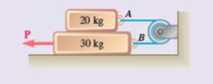
Fig. P8.135
Expert Solution & Answer
Want to see the full answer?
Check out a sample textbook solution
Students have asked these similar questions
Water is at a temperature of 30 C. Plot the height h of the water as a function of the gap w between the two glass plates for 0.4 mm ≤ w ≤ 2.4 mm. Use increments of 0.4mm. Take sigma=0.0718 N/m.
What is the reading on the vernier calipers?
7
6
0 5
10
8
Determine the moments of the force about the x and the
a axes.
O
4 m
F = {-40i +20j + 10k} N
3 m
6 m
a
Chapter 8 Solutions
VECTOR MECHANICS FOR ENGINEERS: STATICS
Ch. 8.1 - Knowing that the coefficient of friction between...Ch. 8.1 - Two blocks A and B are connected by a cable as...Ch. 8.1 - A cord is attached to and partially wound around a...Ch. 8.1 - A 40-kg packing crate must be moved to the left...Ch. 8.1 - Determine whether the block shown is in...Ch. 8.1 - Prob. 8.2PCh. 8.1 - Prob. 8.3PCh. 8.1 - Prob. 8.4PCh. 8.1 - Prob. 8.5PCh. 8.1 - The 20-lb block A hangs from a cable as shown....
Ch. 8.1 - The 10-kg block is attached to link AB and rests...Ch. 8.1 - Considering only values of less than 90,...Ch. 8.1 - The coefficients of friction between the block and...Ch. 8.1 - The coefficients of friction between the block and...Ch. 8.1 - The 50-lb block A and the 25-lb block B are...Ch. 8.1 - The 50-lb block A and the 25-lb block B are...Ch. 8.1 - Three 4-kg packages A, B, and C are placed on a...Ch. 8.1 - Solve Prob. 8.13 assuming that package B is placed...Ch. 8.1 - A uniform crate with a mass of 30 kg must be moved...Ch. 8.1 - A worker slowly moves a 50-kg crate to the left...Ch. 8.1 - Prob. 8.17PCh. 8.1 - A 200-lb sliding door is mounted on a horizontal...Ch. 8.1 - Prob. 8.19PCh. 8.1 - Solve Prob. 8.19 assuming that the coefficients of...Ch. 8.1 - Prob. 8.21PCh. 8.1 - The cylinder shown has a weight W and radius r,...Ch. 8.1 - The 10-lb uniform rod AB is held in the position...Ch. 8.1 - In Prob. 8.23, determine the largest value of P...Ch. 8.1 - A 6. 5-m ladder AB leans against a wall as shown....Ch. 8.1 - A 6. 5-m ladder AB leans against a wall as shown....Ch. 8.1 - The press shown is used to emboss a small seal at...Ch. 8.1 - The machine base shown has a mass of 75 kg and is...Ch. 8.1 - The 50-lb plate ABCD is attached at A and D to...Ch. 8.1 - In Prob. 8.29, determine the range of values of...Ch. 8.1 - A window sash weighing 10 lb is normally supported...Ch. 8.1 - A 500-N concrete block is to be lifted by the pair...Ch. 8.1 - Prob. 8.33PCh. 8.1 - A driver starts the engine of an automobile that...Ch. 8.1 - Prob. 8.35PCh. 8.1 - Prob. 8.36PCh. 8.1 - A 1.2-m plank with a mass of 3 kg rests on two...Ch. 8.1 - Two identical uniform boards, each with a weight...Ch. 8.1 - Prob. 8.39PCh. 8.1 - Prob. 8.40PCh. 8.1 - A 10-ft beam, weighing 1200 lb, is to be moved to...Ch. 8.1 - (a) Show that the beam of Prob. 8.41 cannot be...Ch. 8.1 - Two 8-kg blocks A and B resting on shelves are...Ch. 8.1 - A slender steel rod with a length of 225 mm is...Ch. 8.1 - In Prob. 8.44, determine the smallest value of ...Ch. 8.1 - Two slender rods of negligible weight are...Ch. 8.1 - Two slender rods of negligible weight are...Ch. 8.2 - The machine part ABC is supported by a...Ch. 8.2 - Solve Prob. 8.48 assuming that the wedge is moved...Ch. 8.2 - 8.50 and 8.51 Two 6 wedges of negligible weight...Ch. 8.2 - 8.50 and 8.51 Two 6 wedges of negligible weight...Ch. 8.2 - The elevation of the end of the steel beam...Ch. 8.2 - Prob. 8.53PCh. 8.2 - Block A supports a pipe column and rests as shown...Ch. 8.2 - Block A supports a pipe column and rests as shown...Ch. 8.2 - Block A supports a pipe column and rests as shown...Ch. 8.2 - A 200-lb block rests as shown on a wedge of...Ch. 8.2 - A 15 wedge is forced into a saw cut to prevent...Ch. 8.2 - A 12 wedge is used to spread a split ring. The...Ch. 8.2 - The spring of the door latch has a constant of 1.8...Ch. 8.2 - Prob. 8.61PCh. 8.2 - Prob. 8.62PCh. 8.2 - Prob. 8.63PCh. 8.2 - A 15 wedge is forced under a 50-kg pipe as shown....Ch. 8.2 - A 15 wedge is forced under a 50-kg pipe as shown....Ch. 8.2 - Prob. 8.66PCh. 8.2 - Prob. 8.67PCh. 8.2 - Derive the following formulas relating the load W...Ch. 8.2 - The square-threaded worm gear shown has a mean...Ch. 8.2 - Prob. 8.70PCh. 8.2 - High-strength bolts are used in the construction...Ch. 8.2 - The position of the automobile jack shown is...Ch. 8.2 - For the jack of Prob. 8.72, determine the...Ch. 8.2 - Prob. 8.74PCh. 8.2 - Prob. 8.75PCh. 8.2 - Prob. 8.76PCh. 8.3 - A lever of negligible weight is loosely fitted...Ch. 8.3 - A 6-in.-radius pulley of weight 5 lb is attached...Ch. 8.3 - 8.79 and 8.80 The double pulley shown is attached...Ch. 8.3 - Prob. 8.80PCh. 8.3 - 8.81 and 8.82 The double pulley shown is attached...Ch. 8.3 - 8.81 and 8.82 The double pulley shown is attached...Ch. 8.3 - The block and tackle shown are used to raise a...Ch. 8.3 - The block and tackle shown are used to lower a...Ch. 8.3 - A scooter is to be designed to roll down a 2...Ch. 8.3 - The link arrangement shown is frequently used in...Ch. 8.3 - 8.87 and 8.88 A lever AB of negligible weight is...Ch. 8.3 - 8.87 and 8.88 A lever AB of negligible weight is...Ch. 8.3 - 8.89 and 8.90 A lever AB of negligible weight is...Ch. 8.3 - 8.89 and 8.90 A lever AB of negligible weight is...Ch. 8.3 - A loaded railroad car has a mass of 30 Mg and is...Ch. 8.3 - Prob. 8.92PCh. 8.3 - A 50-lb electric floor polisher is operated on a...Ch. 8.3 - The frictional resistance of a thrust bearing...Ch. 8.3 - Assuming that bearings wear out as indicated in...Ch. 8.3 - Assuming that the pressure between the surfaces of...Ch. 8.3 - Solve Prob. 8.93 assuming that the normal force...Ch. 8.3 - Determine the horizontal force required to move a...Ch. 8.3 - Knowing that a 6-in.-diameter disk rolls at a...Ch. 8.3 - A 900-kg machine base is rolled along a concrete...Ch. 8.3 - Solve Prob. 8.85 including the effect of a...Ch. 8.3 - Solve Prob. 8.91 including the effect of a...Ch. 8.4 - A rope having a weight per unit length of 0.4...Ch. 8.4 - A hawser is wrapped two full turns around a...Ch. 8.4 - Two cylinders are connected by a rope that passes...Ch. 8.4 - Two cylinders are connected by a rope that passes...Ch. 8.4 - The coefficient of static friction between block B...Ch. 8.4 - The coefficient of static friction S is the same...Ch. 8.4 - A band belt is used to control the speed of a...Ch. 8.4 - The setup shown is used to measure the output of a...Ch. 8.4 - The setup shown is used to measure the output of a...Ch. 8.4 - A flat belt is used to transmit a couple from drum...Ch. 8.4 - A flat belt is used to transmit a couple from...Ch. 8.4 - Prob. 8.114PCh. 8.4 - The speed of the brake drum shown is controlled by...Ch. 8.4 - Prob. 8.116PCh. 8.4 - The speed of the brake drum shown is controlled by...Ch. 8.4 - Bucket A and block C are connected by a cable that...Ch. 8.4 - Solve Prob. 8.118 assuming that drum B is frozen...Ch. 8.4 - Prob. 8.120PCh. 8.4 - 8.121 and 8.123 A cable is placed around three...Ch. 8.4 - Prob. 8.122PCh. 8.4 - 8.121 and 8.123 A cable is placed around three...Ch. 8.4 - A recording tape passes over the 20-mm-radius...Ch. 8.4 - Solve Prob. 8.124 assuming that the idler drum C...Ch. 8.4 - Prob. 8.126PCh. 8.4 - The axle of the pulley is frozen and cannot rotate...Ch. 8.4 - Prob. 8.128PCh. 8.4 - Prob. 8.129PCh. 8.4 - Prove that Eqs. (8.13) and (8.14) are valid for...Ch. 8.4 - Prob. 8.131PCh. 8.4 - Solve Prob. 8.112 assuming that the flat belt and...Ch. 8.4 - Solve Prob. 8.113 assuming that the flat belt and...Ch. 8 - 8.134 and 8.135 The coefficients of friction are S...Ch. 8 - 8.134 and 8.135 The coefficients of friction are S...Ch. 8 - A 120-lb cabinet is mounted on casters that can be...Ch. 8 - Prob. 8.137RPCh. 8 - The hydraulic cylinder shown exerts a force of 3...Ch. 8 - Prob. 8.139RPCh. 8 - Bar AB is attached to collars that can slide on...Ch. 8 - Two 10 wedges of negligible weight are used to...Ch. 8 - A 10 wedge is used to split a section of a log....Ch. 8 - In the gear-pulling assembly shown, the...Ch. 8 - A lever of negligible weight is loosely fitted...Ch. 8 - In the pivoted motor mount shown, the weight W of...
Knowledge Booster


Learn more about
Need a deep-dive on the concept behind this application? Look no further. Learn more about this topic, mechanical-engineering and related others by exploring similar questions and additional content below.Similar questions
- 6. A part of the structure for a factory automation system is a beam that spans 30.0 in as shown in Figure P5-6. Loads are applied at two points, each 8.0 in from a support. The left load F₁ = 1800 lb remains constantly applied, while the right load F₂ = 1800 lb is applied and removed fre- quently as the machine cycles. Evaluate the beam at both B and C. A 8 in F₁ = 1800 lb 14 in F2 = 1800 lb 8 in D RA B C 4X2X1/4 Steel tube Beam cross section RDarrow_forward30. Repeat Problem 28, except using a shaft that is rotating and transmitting a torque of 150 N⚫m from the left bear- ing to the middle of the shaft. Also, there is a profile key- seat at the middle under the load.arrow_forward28. The shaft shown in Figure P5-28 is supported by bear- ings at each end, which have bores of 20.0 mm. Design the shaft to carry the given load if it is steady and the shaft is stationary. Make the dimension a as large as pos- sible while keeping the stress safe. Determine the required d = 20mm D = ? R = ?| 5.4 kN d=20mm Length not to scale -a = ?- +а= a = ? + -125 mm- -250 mm- FIGURE P5-28 (Problems 28, 29, and 30)arrow_forward
- 12. Compute the estimated actual endurance limit for SAE 4130 WQT 1300 steel bar with a rectangular cross sec- tion of 20.0 mm by 60 mm. It is to be machined and subjected to repeated and reversed bending stress. A reli- ability of 99% is desired.arrow_forward28. The shaft shown in Figure P5-28 is supported by bear- ings at each end, which have bores of 20.0 mm. Design the shaft to carry the given load if it is steady and the shaft is stationary. Make the dimension a as large as pos- sible while keeping the stress safe. Determine the required d = 20mm D = ? R = ?| 5.4 kN d=20mm Length not to scale -a = ?- +а= a = ? + -125 mm- -250 mm- FIGURE P5-28 (Problems 28, 29, and 30)arrow_forward2. A strut in a space frame has a rectangular cross section of 10.0 mm by 30.0 mm. It sees a load that varies from a tensile force of 20.0 kN to a compressive force of 8.0 kN.arrow_forward
- find stress at Qarrow_forwardI had a theoretical question about attitude determination. In the attached images, I gave two axis and angles. The coefficient of the axes are the same and the angles are the same. The only difference is the vector basis. Lets say there is a rotation going from n hat to b hat. Then, you introduce a intermediate rotation s hat. So, I want to know if the DCM produced from both axis and angles will be the same or not. Does the vector basis affect the numerical value of the DCM? The DCM formula only cares about the coefficient of the axis and the angle. So, they should be the same right?arrow_forward3-15. A small fixed tube is shaped in the form of a vertical helix of radius a and helix angle y, that is, the tube always makes an angle y with the horizontal. A particle of mass m slides down the tube under the action of gravity. If there is a coefficient of friction μ between the tube and the particle, what is the steady-state speed of the particle? Let y γ 30° and assume that µ < 1/√3.arrow_forward
- The plate is moving at 0.6 mm/s when the force applied to the plate is 4mN. If the surface area of the plate in contact with the liquid is 0.5 m^2, deterimine the approximate viscosity of the liquid, assuming that the velocity distribution is linear.arrow_forward3-9. Given that the force acting on a particle has the following components: Fx = −x + y, Fy = x − y + y², F₂ = 0. Solve for the potential energy V. -arrow_forward2.5 (B). A steel rod of cross-sectional area 600 mm² and a coaxial copper tube of cross-sectional area 1000 mm² are firmly attached at their ends to form a compound bar. Determine the stress in the steel and in the copper when the temperature of the bar is raised by 80°C and an axial tensile force of 60 kN is applied. For steel, E = 200 GN/m² with x = 11 x 10-6 per °C. E = 100 GN/m² with α = 16.5 × 10⁻⁶ For copper, per °C. [E.I.E.] [94.6, 3.3 MN/m².]arrow_forward
arrow_back_ios
SEE MORE QUESTIONS
arrow_forward_ios
Recommended textbooks for you
 Elements Of ElectromagneticsMechanical EngineeringISBN:9780190698614Author:Sadiku, Matthew N. O.Publisher:Oxford University Press
 Mechanics of Materials (10th Edition)Mechanical EngineeringISBN:9780134319650Author:Russell C. HibbelerPublisher:PEARSON
 Thermodynamics: An Engineering ApproachMechanical EngineeringISBN:9781259822674Author:Yunus A. Cengel Dr., Michael A. BolesPublisher:McGraw-Hill Education
 Control Systems EngineeringMechanical EngineeringISBN:9781118170519Author:Norman S. NisePublisher:WILEY
 Mechanics of Materials (MindTap Course List)Mechanical EngineeringISBN:9781337093347Author:Barry J. Goodno, James M. GerePublisher:Cengage Learning
 Engineering Mechanics: StaticsMechanical EngineeringISBN:9781118807330Author:James L. Meriam, L. G. Kraige, J. N. BoltonPublisher:WILEY
Elements Of Electromagnetics
Mechanical Engineering
ISBN:9780190698614
Author:Sadiku, Matthew N. O.
Publisher:Oxford University Press
Mechanics of Materials (10th Edition)
Mechanical Engineering
ISBN:9780134319650
Author:Russell C. Hibbeler
Publisher:PEARSON
Thermodynamics: An Engineering Approach
Mechanical Engineering
ISBN:9781259822674
Author:Yunus A. Cengel Dr., Michael A. Boles
Publisher:McGraw-Hill Education
Control Systems Engineering
Mechanical Engineering
ISBN:9781118170519
Author:Norman S. Nise
Publisher:WILEY
Mechanics of Materials (MindTap Course List)
Mechanical Engineering
ISBN:9781337093347
Author:Barry J. Goodno, James M. Gere
Publisher:Cengage Learning
Engineering Mechanics: Statics
Mechanical Engineering
ISBN:9781118807330
Author:James L. Meriam, L. G. Kraige, J. N. Bolton
Publisher:WILEY
Introduction to Undamped Free Vibration of SDOF (1/2) - Structural Dynamics; Author: structurefree;https://www.youtube.com/watch?v=BkgzEdDlU78;License: Standard Youtube License