
EBK MECHANICS OF MATERIALS
7th Edition
ISBN: 8220100257063
Author: BEER
Publisher: YUZU
expand_more
expand_more
format_list_bulleted
Videos
Textbook Question
Chapter 8, Problem 76RP
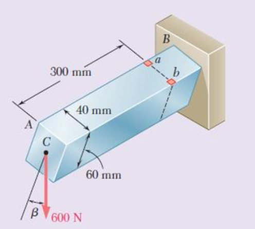
The cantilever beam AB will be installed so that the 60-mm side forms an angle b between 0 and 90° with the vertical. Knowing that the 600-N vertical force is applied at the center of the free end of the beam, determine the normal stress at point a when (a) β = 0, (b) β = 90°. (c) Also, determine the value of β for which the normal stress at point a is a maximum and the corresponding value of that stress.
Fig. P8.76
Expert Solution & Answer
Want to see the full answer?
Check out a sample textbook solution
Students have asked these similar questions
13.38 Consider the attic of a home located in a hot climate.
The floor of the attic is characterized by a width of
L₁ = 8 m while the roof makes an angle of 0 = 30° from
the horizontal direction, as shown in the schematic.
The homeowner wishes to reduce the heat load to the
home by adhering bright aluminum foil (ε = 0.07) onto
the surfaces of the attic space. Prior to installation of
the foil, the surfaces are of emissivity & = 0.90.
Attic
A2, 82, T2 0 = 30°
A1, E1, T₁
土
L₁ = 8 m
(a) Consider installation on the bottom of the attic
roof only. Determine the ratio of the radiation heat
transfer after to before the installation of the foil.
(b) Determine the ratio of the radiation heat transfer
after to before installation if the foil is installed
only on the top of the attic floor.
(c) Determine the ratio of the radiation heat transfer if
the foil is installed on both the roof bottom and the
floor top.
13.1
Determine F2 and F2 for the following configura-
tions using the reciprocity theorem and other basic
shape factor relations. Do not use tables or charts.
(a) Small sphere of area A, under a concentric hemi-
sphere of area A₂ = 3A₁
A₂
A1
(a)
(b) Long duct. Also, what is F₁₂?
A₂
Αν
(b)
(c) Long inclined plates (point B is directly above the
center of A₁)
B
100 mm
A₂
- 220 mm
(c)
(d) Long cylinder lying on infinite plane
+
A₁
Az
(d)
(e) Hemisphere-disk arrangement
-A₂, hemisphere,
diameter D
A₂
A₁, disk,
diameter D/2
(e)
(f) Long, open channel
1 m
AA₂
2 m
(f)
(g) Long cylinders with A₁ = 4A₁. Also, what is F₁₂?
-D₁
A1
-A₂
-D2
(e)
(h) Long, square rod in a long cylinder. Also, what
is F22?
w=D/5
18
A₁
-A2
(h)
-D
13.9 Determine the shape factor, F12, for the rectangles
shown.
6 m
1
3 m
6 m
1 m
2
6 m
1
0.5 m
2
1 m
(a) Perpendicular rectangles
without a common edge.
-1 m.
(b) Parallel rectangles of
unequal areas.
Chapter 8 Solutions
EBK MECHANICS OF MATERIALS
Ch. 8.2 - A W10 = 39 rolled-steel beam supports a load P as...Ch. 8.2 - Solve Prob. 8.1, assuming that P = 22.5 kips and a...Ch. 8.2 - An overhanging W920 449 rolled-steel beam...Ch. 8.2 - Solve Prob. 8.3, assuming that P = 850 kN and a =...Ch. 8.2 - 8.5 and 8.6 (a) Knowing that all = 160 MPa and all...Ch. 8.2 - 8.5 and 8.6 (a) Knowing that all = 160 MPa and all...Ch. 8.2 - 8.7 and 8.8 (a) Knowing that all = 24 ksi and all...Ch. 8.2 - 8.7 and 8.8 (a) Knowing that all = 24 ksi and all...Ch. 8.2 - 8.9 through 8.14 Each of the following problems...Ch. 8.2 - 8.9 through 8.14 Each of the following problems...
Ch. 8.2 - 8.9 through 8.14 Each of the following problems...Ch. 8.2 - Prob. 12PCh. 8.2 - 8.9 through 8.14 Each of the following problems...Ch. 8.2 - 8.9 through 8.14 Each of the following problems...Ch. 8.2 - Determine the smallest allowable diameter of the...Ch. 8.2 - Determine the smallest allowable diameter of the...Ch. 8.2 - Using the notation of Sec. 8.2 and neglecting the...Ch. 8.2 - The 4-kN force is parallel to the x axis, and the...Ch. 8.2 - The vertical force P1 and the horizontal force P2...Ch. 8.2 - The two 500-lb forces are vertical and the force P...Ch. 8.2 - Prob. 21PCh. 8.2 - Prob. 22PCh. 8.2 - The solid shaft AB rotates at 600 rpm and...Ch. 8.2 - The solid shaft AB rotates at 600 rpm and...Ch. 8.2 - The solid shafts ABC and DEF and the gears shown...Ch. 8.2 - Prob. 26PCh. 8.2 - Prob. 27PCh. 8.2 - Prob. 28PCh. 8.2 - The solid shaft AE rotates at 600 rpm and...Ch. 8.2 - The solid shaft AE rotates at 600 rpm and...Ch. 8.3 - Two 1.2-kip forces are applied to an L-shaped...Ch. 8.3 - Two 1.2-kip forces are applied to an L-shaped...Ch. 8.3 - The cantilever beam AB has a rectangular cross...Ch. 8.3 - 8.34 through 8.36 Member AB has a uniform...Ch. 8.3 - 8.34 through 8.36 Member AB has a uniform...Ch. 8.3 - 8.34 through 8.36 Member AB has a uniform...Ch. 8.3 - Prob. 37PCh. 8.3 - Two forces are applied to the pipe AB as shown....Ch. 8.3 - Several forces are applied to the pipe assembly...Ch. 8.3 - The steel pile AB has a 100-mm outer diameter and...Ch. 8.3 - Three forces are applied to a 4-in.-diameter plate...Ch. 8.3 - The steel pipe AB has a 72-mm outer diameter and a...Ch. 8.3 - A 13-kN force is applied as shown to the...Ch. 8.3 - A vertical force P of magnitude 60 lb is applied...Ch. 8.3 - Three forces are applied to the bar shown....Ch. 8.3 - Prob. 46PCh. 8.3 - Three forces are applied to the bar shown....Ch. 8.3 - Three forces are applied to the bar shown....Ch. 8.3 - Two forces are applied to the small post BD as...Ch. 8.3 - Two forces are applied to the small post BD as...Ch. 8.3 - Three forces are applied to the machine component...Ch. 8.3 - Prob. 52PCh. 8.3 - Three steel plates, each 13 mm thick, are welded...Ch. 8.3 - Three steel plates, each 13 mm thick, are welded...Ch. 8.3 - Two forces P1 and P2 are applied as shown in...Ch. 8.3 - Two forces P1 and P2 are applied as shown in...Ch. 8.3 - Prob. 57PCh. 8.3 - Four forces are applied to a W8 28 rolled-steel...Ch. 8.3 - A force P is applied to a cantilever beam by means...Ch. 8.3 - Prob. 60PCh. 8.3 - A 5-kN force P is applied to a wire that is...Ch. 8.3 - Knowing that the structural tube shown has a...Ch. 8.3 - The structural tube shown has a uniform wall...Ch. 8.3 - The structural tube shown has a uniform wall...Ch. 8 - (a) Knowing that all = 24 ksi and all = 14.5 ksi,...Ch. 8 - Neglecting the effect of fillets and of stress...Ch. 8 - Knowing that rods BC and CD are of diameter 24 mm...Ch. 8 - The solid shaft AB rotates at 450 rpm and...Ch. 8 - A 6-kip force is applied to the machine element AB...Ch. 8 - A thin strap is wrapped around a solid rod of...Ch. 8 - A close-coiled spring is made of a circular wire...Ch. 8 - Forces are applied at points A and B of the solid...Ch. 8 - Knowing that the bracket AB has a uniform...Ch. 8 - For the post and loading shown, determine the...Ch. 8 - Knowing that the structural tube shown has a...Ch. 8 - The cantilever beam AB will be installed so that...
Knowledge Booster


Learn more about
Need a deep-dive on the concept behind this application? Look no further. Learn more about this topic, mechanical-engineering and related others by exploring similar questions and additional content below.Similar questions
- I keep getting the wrong answer i have gotten 6519.87 and 319.71arrow_forwardthank you for previous answer I apologize if the acceleration was unclear it is underlined now along with values in tablesarrow_forward११११११११ TABLE Much 160,000kg Croll 0,005 CD Ap Par ng При nchs 0.15 5m² 1.2kg/m³ 0.98 0.9 0,98 0,9 0,88 IF 20 10 to add The train is going to make several stops along its journey. It will be important for the train to accelerate quickdy to get back up to speed. In order to get Tesla Model S motors until we get the combined The Forque and power needed we are goins bined power and forque needed to accelerate from 0 to 324 km/hr in less than 5 Minutes. Tesla Prated 270 kW Tesla Trated Twheel ng Jaxle 440 NM 20 8.5kgm² 0.45M a) What is the minimum whole number of Tesla Motors required to achieve accelerate the train from 0 to 324 km/hr in less than 5 Nnutes? Seperate the acceleration into constant torque and constant power 0. b) How long does it take the train to accelerate from 0 to 324 km/hr with the number of Tesla motors from part a? c) Using Matlab plot the relocity profile as a function of time, Is this a constant acceleration profile? Barrow_forward
- Example find f(t)? -4s F(s)= (s² + 4)²arrow_forwarddraw a kinematic diagramarrow_forwardRigid bodies ENG2016. Full complete solutions need okk don't use guidelines but solve full accurate steps by steps don't use chat gpt or any other ai okkk just solve complete solutions okkk take your time but solve complete solutionsarrow_forward
- Question 6 I need to show all work step by step dynamicsarrow_forwardQu. 3 The automobile is originally at rest s = 0. If it then starts to increase its speed at i = (0.05t2)ft/s?, where t is in seconds, determine the magnitudes of its velocity and acceleration at s = 550 ft. please show all work from dynamics step by step formulaarrow_forwardquestion 5 and 6 from dynamics I need to show all work step by step problemsarrow_forward
- Study Area Document Sharing User Settings Access Pearson mylabmastering.pearson.com P Pearson MyLab and Mastering The crash cushion for a highway barrier consists of a nest of barrels filled with an impact-absorbing material. The barrier stopping force is measured versus the vehicle penetration into the barrier. (Figure 1) Part A P Course Home b My Questions | bartleby Review Determine the distance a car having a weight of 4000 lb will penetrate the barrier if it is originally traveling at 55 ft/s when it strikes the first barrel. Express your answer to three significant figures and include the appropriate units. Figure 1 of 1 36 μΑ S = Value Units Submit Request Answer Provide Feedback ? Next >arrow_forwardWater is the working fluid in an ideal Rankine cycle. Saturated vapor enters the turbine at 12 MPa, and the condenser pressure is 8 kPa. The mass flow rate of steam entering the turbine is 50 kg/s. Determine: (a) the net power developed, in kW. (b) the rate of heat transfer to the steam passing through the boiler, in kW. (c) the percent thermal efficiency. (d) the mass flow rate of condenser cooling water, in kg/s, if the cooling water undergoes a temperature increase of 18°C with negligible pressure change in passing through the condenser.arrow_forward4. The figure below shows a bent pipe with the external loading FA 228 lb, and M₁ = M₂ = 1 kip-ft. The force Fernal loading FA = 300 lb, FB: parallel to the y-axis, and and yc = 60°. = 125 lb, Fc = acts parallel to the x-z plane, the force FB acts Cartesian resultan Coordinate direction angles of Fc are ac = 120°, ẞc = 45°, a. Compute the resultant force vector of the given external loading and express it in EST form. b. Compute the resultant moment vector of the given external loading about the origin, O, and express it in Cartesian vector form. Use the vector method while computing the moments of forces. c. Compute the resultant moment vector of the given external loading about the line OA and express it in Cartesian vector form. :00 PM EST k ghoufran@buffaternal du 2 ft M₁ A 40° FA M2 C 18 in 1 ft Fc 25 houfran@bald.edu - Feb 19, 3 ft FBarrow_forward
arrow_back_ios
SEE MORE QUESTIONS
arrow_forward_ios
Recommended textbooks for you
 Elements Of ElectromagneticsMechanical EngineeringISBN:9780190698614Author:Sadiku, Matthew N. O.Publisher:Oxford University Press
 Mechanics of Materials (10th Edition)Mechanical EngineeringISBN:9780134319650Author:Russell C. HibbelerPublisher:PEARSON
 Thermodynamics: An Engineering ApproachMechanical EngineeringISBN:9781259822674Author:Yunus A. Cengel Dr., Michael A. BolesPublisher:McGraw-Hill Education
 Control Systems EngineeringMechanical EngineeringISBN:9781118170519Author:Norman S. NisePublisher:WILEY
 Mechanics of Materials (MindTap Course List)Mechanical EngineeringISBN:9781337093347Author:Barry J. Goodno, James M. GerePublisher:Cengage Learning
 Engineering Mechanics: StaticsMechanical EngineeringISBN:9781118807330Author:James L. Meriam, L. G. Kraige, J. N. BoltonPublisher:WILEY
Elements Of Electromagnetics
Mechanical Engineering
ISBN:9780190698614
Author:Sadiku, Matthew N. O.
Publisher:Oxford University Press
Mechanics of Materials (10th Edition)
Mechanical Engineering
ISBN:9780134319650
Author:Russell C. Hibbeler
Publisher:PEARSON
Thermodynamics: An Engineering Approach
Mechanical Engineering
ISBN:9781259822674
Author:Yunus A. Cengel Dr., Michael A. Boles
Publisher:McGraw-Hill Education
Control Systems Engineering
Mechanical Engineering
ISBN:9781118170519
Author:Norman S. Nise
Publisher:WILEY
Mechanics of Materials (MindTap Course List)
Mechanical Engineering
ISBN:9781337093347
Author:Barry J. Goodno, James M. Gere
Publisher:Cengage Learning
Engineering Mechanics: Statics
Mechanical Engineering
ISBN:9781118807330
Author:James L. Meriam, L. G. Kraige, J. N. Bolton
Publisher:WILEY
Mechanics of Materials Lecture: Beam Design; Author: UWMC Engineering;https://www.youtube.com/watch?v=-wVs5pvQPm4;License: Standard Youtube License