
Concept explainers
The switch in Fig. 8.70 is moved from A to B at t = 0 after being at A for a long time. This places the two capacitors in series, thus allowing equal and opposite dc voltages to be trapped on the capacitors. (a) Determine v1(0−), v2(0−), and vR(0−). (b) Find v1(0+), v2(0+), and vR(0+). (c) Determine the time constant of vR(t). (d) Find vR(t), t > 0. (e) Find i(t). (f) Find v1(t) and v2(t) from i(t) and the initial values. (g) Show that the stored energy at t = ∞ plus the total energy dissipated in the 20 kΩ resistor is equal to the energy stored in the capacitors at t = 0.
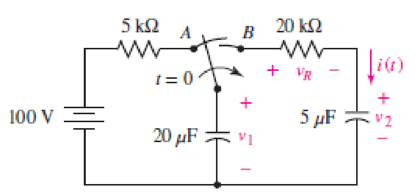
■ FIGURE 8.70
(a)
Find the value of
Answer to Problem 38E
The value of
Explanation of Solution
Given data:
Refer to Figure 8.70 in the textbook.
The switch is moved from
Calculation:
The given circuit is redrawn as shown in Figure 1.
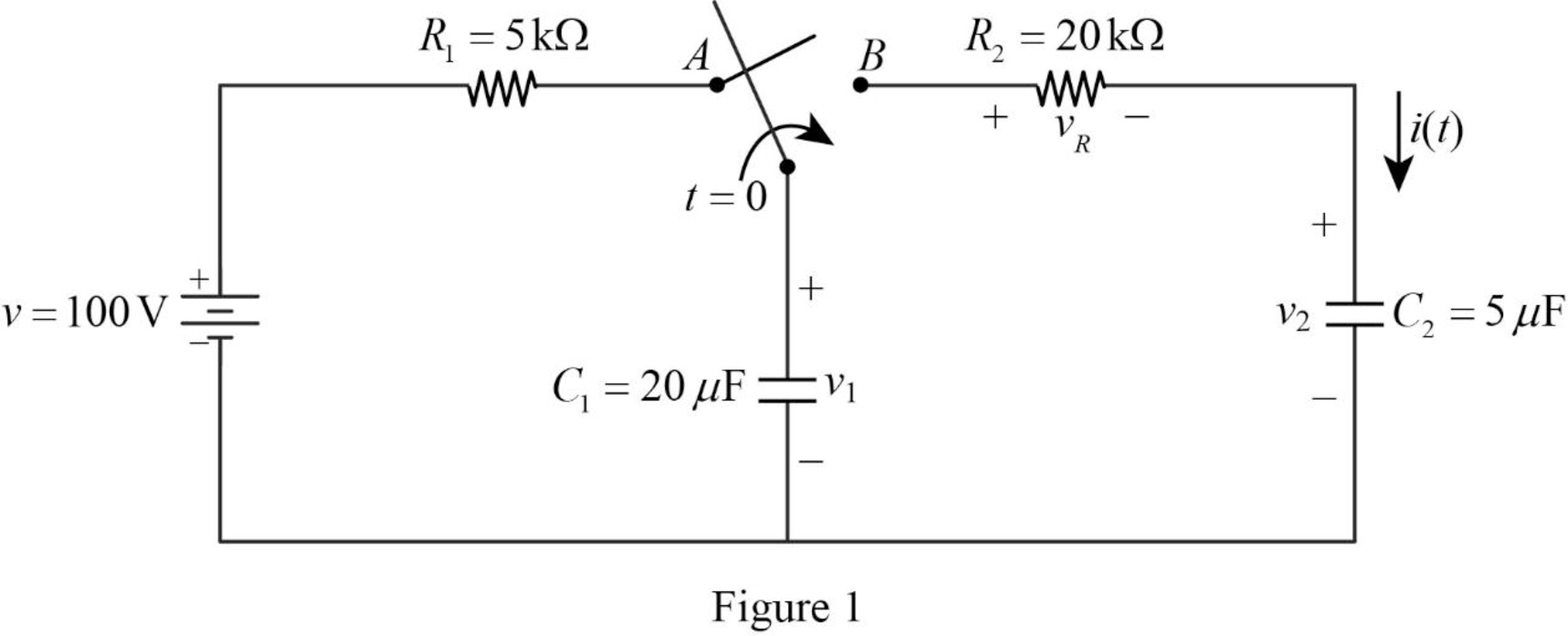
Refer to Figure 1, the voltage across the capacitor
For a DC circuit at steady state condition, when the switch is in position
Now, the Figure 1 is reduced as shown in Figure 2.
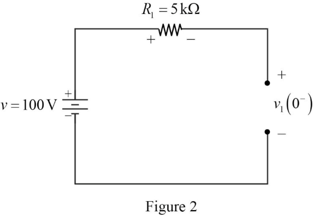
Refer to Figure 2, the voltage source
The voltage across the capacitor
Refer to Figure 2, the resistor
The voltage across the capacitor is always continuous so that,
Conclusion:
Thus, the value of
(b)
Find the value of
Answer to Problem 38E
The value of
Explanation of Solution
Calculation:
For time
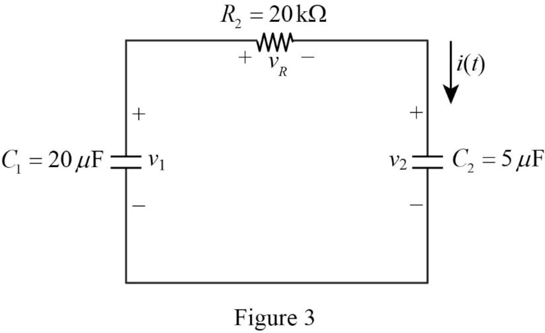
Refer to part (a),
Apply Kirchhoff’s voltage for the circuit shown in Figure 3 for time
Substitute
Conclusion:
Thus, the value of
(c)
Find the value of the time constant.
Answer to Problem 38E
The value of time constant
Explanation of Solution
Formula used:
Write a general expression to calculate the time constant.
Here,
Calculation:
Refer to Figure 3, the capacitors
The equivalent capacitance
Now, the Figure 3 is reduced as shown in Figure 4.
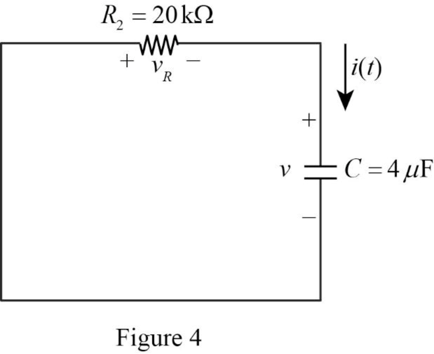
Refer to Figure 4, it shows the
Use equation (1) to find
Substitute
Conclusion:
Thus, the value of time constant
(d)
Find the expression of voltage
Answer to Problem 38E
The expression of voltage
Explanation of Solution
Formula used:
Write a general expression to calculate the voltage response of an
Here,
Refer to Figure 3, the resistor
Substitute
Substitute
Conclusion:
Thus, the expression of voltage
(e)
Find the expression of current
Answer to Problem 38E
The expression of current
Explanation of Solution
Calculation:
Refer to Figure 3, the capacitor
The current
Substitute
Conclusion:
Thus, the expression of current
(f)
Find the value of voltage
Answer to Problem 38E
The value of voltage
Explanation of Solution
Formula used:
Write a general expression to calculate the voltage across the capacitor.
Calculation:
From the given data, the capacitor
Use equation (1) to find the voltage
Substitute
Simplify the above equation to find
Use equation (1) to find the voltage
Substitute
Simplify the above equation to find
Conclusion:
Thus, the value of voltage
(g)
Show that the stored energy at
Explanation of Solution
Formula used:
Write a general expression to calculate the energy stored in a capacitor.
Write a general expression to calculate the energy stored in a resistor.
Here,
Calculation:
Refer to Figure 1, there are two capacitors placed in a circuit. Therefore, the total energy stored in a capacitor is,
Use equation (1) to find
Use equation (1) to find
Substitute equation (7) and (8) in (6).
Substitute
Substitute
Simplify the above equation to find
Refer to part (f),
Substitute
Refer to part (f),
Substitute
Substitute
Substitute
Simplify the above equation to find
Substitute
Simplify the above equation to find
Simplify the above equation to find
Substitute
Add
Therefore,
Therefore, the stored energy at
Conclusion:
Thus, the stored energy at
Want to see more full solutions like this?
Chapter 8 Solutions
Loose Leaf for Engineering Circuit Analysis Format: Loose-leaf
- I need a drawing on how to connect the function generator, oscilliscope, and both multimeters. It is hard for me to follow text instructions. The function generator has a postive,common and negative. The oscilliscope has chanell A and B, both channels have a postive and a negative. I know you can provide text instruction but a little sketch would be very helpful thank you.arrow_forwardDon't use ai to answer I will report you answerarrow_forwardQ1/ A three phase, 500 kVA, 6600 V, 50 Hz, 6 pole, star connected synchronous motor has synchronous impedance of J 70 ohm per phase at its normal rating, the motor is excited to give unity power factor at the input terminals. Find a) The rated current and power factor. b) The emf behind the synchronous impedance. c) The developed torque. d) The pull out torque. e) The increase in excitation which will just permit an increase of 30% of rated torque before pulling out of synchronism. (45 M.)arrow_forward
- can you fin Vds and Vgs of all transistors and specify te operating region off all transistors and prove it. 58V 5.8 V 1.8V M2 0.9V 22222 と A 4852 m 3 01 A Voy = 0.2 V V4)=0.SV λ=0.1 V-1arrow_forwardNeed a aolarrow_forward2 Find Inverse Fourier transform of F(jw) = 2w -16+w2, and plot the f(t).arrow_forward
 Delmar's Standard Textbook Of ElectricityElectrical EngineeringISBN:9781337900348Author:Stephen L. HermanPublisher:Cengage Learning
