
Concept explainers
Videos
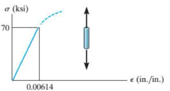
The elastic portion of the tension stress-strain diagram for an aluminum alloy is shown in the figure. The specimen used for the test has a gage length of 2 in. and a diameter of 0,5 in. When the applied load is 9 kip, the new diameter of the specimen is 0.49935 in. Calculate the shear modulus Gal for the aluminum.
Probs. R8-1/2
Find the shear modulus for an aluminum alloy
Answer to Problem 1RP
The shear modulus for an aluminum alloy is
Explanation of Solution
Given information:
Gage length is 2 in..
The diameter of the specimen is 0.5 in..
The axial load acts on the specimen is 9 kips..
The new diameter of the specimen is 0.49935 in.
Calculation:
Calculate the modulus of elasticity for aluminum
Here, the stress is
Refer the stress-strain diagram.
The value of stress is 70 ksi and the value of strain is
Substitute 70 ksi for
The expression to find the cross-sectional area of the specimen
Here, the diameter of the specimen is d.
Substitute 0.5 in. for d.
Find the value of stress when the specimen is loaded with a 9 kip load using the relation:
Here, the load is P.
Substitute 9 kip for P and
The expression to find the strain in the longitudinal or axial direction
Here, the Young’s modulus of the aluminum is E.
Substitute 45.84 ksi for
Find the strain in lateral direction
Here, the new diameter is
Substitute 0.49935 in. for
Find the Poisson’s ratio
Substitute
Calculate the modulus of rigidity for the specimen
Substitute 11,400.65 ksi for
Therefore, the shear modulus for an aluminum alloy is
Want to see more full solutions like this?
Chapter 8 Solutions
Statics and Mechanics of Materials (5th Edition)


- My ID#016948724 please solve this problems and show me every step clear to follow pleasearrow_forwardMy ID# 016948724arrow_forwardPlease do not use any AI tools to solve this question. I need a fully manual, step-by-step solution with clear explanations, as if it were done by a human tutor. No AI-generated responses, please.arrow_forward
- Please do not use any AI tools to solve this question. I need a fully manual, step-by-step solution with clear explanations, as if it were done by a human tutor. No AI-generated responses, please.arrow_forwardPlease do not use any AI tools to solve this question. I need a fully manual, step-by-step solution with clear explanations, as if it were done by a human tutor. No AI-generated responses, please.arrow_forward[Q2]: The cost information supplied by the cost accountant is as follows:Sales 20,00 units, $ 10 per unitCalculate the (a/ newsale guantity and (b) new selling price to earn the sameVariable cost $ 6 per unit, Fixed Cost $ 30,000, Profit $ 50,000profit ifi) Variable cost increases by $ 2 per unitil) Fixed cost increase by $ 10,000Ili) Variable cost increase by $ 1 per unit and fixed cost reduces by $ 10,000arrow_forward
- can you please help me perform Visual Inspection and Fractography of the attatched image: Preliminary examination to identify the fracture origin, suspected fatigue striation, and corrosion evidences.arrow_forwardcan you please help[ me conduct Causal Analysis (FTA) on the scenario attatched: FTA diagram which is a fault tree analysis diagram will be used to gain an overview of the entire path of failure from root cause to the top event (i.e., the swing’s detachment) and to identify interactions between misuse, material decay and inspection errors.arrow_forwardhi can you please help me in finding the stress intensity factor using a k-calcluator for the scenario attathced in the images.arrow_forward
 Mechanics of Materials (MindTap Course List)Mechanical EngineeringISBN:9781337093347Author:Barry J. Goodno, James M. GerePublisher:Cengage Learning