
Concept explainers
Videos
The 10-ft cable AB is attached to two collars as shown. The collar at A can slide freely along the rod; a stop attached to the rod prevents the collar at B from moving on the rod. Neglecting the effect of friction and the weight of the collars, determine the distance a.
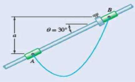
Fig. P7.147
Find the distance a.
Answer to Problem 7.147P
The distance a is
Explanation of Solution
Given information:
The length of the cable AB is
The value of angle
The collar at A is slides freely and the collar at B is prevented from the moving.
Calculation:
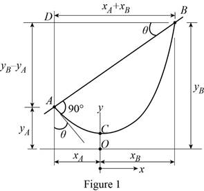
Show the free-body diagram of the cable assembly as in Figure 1.
Refer the Equation 7.16 in the textbook.
Write the equation of the catenary cable as follows;
Differentiate the equation with x;
The slope at point A is;
The length of the portion AC is as follows:
The length of the portion CB is as follows:
Find the distance
Substitute 10 ft for L,
Find the distance
Find the distance
Consider the triangle ABD;
Find the value of
Find the distance a using the relation.
Use the trial and error procedure to find the value of a.
Consider the value of c and for the given value of
Trial 1:
Consider a trial value of 1.60 ft for c.
Substitute 1.60 ft for c and
Substitute 1.60 ft for c and 2.107 ft for
Substitute 1.60 ft for c and 2.107 ft for
Substitute 1.60 ft for c and 3.541 ft for
Substitute 2.107 ft for
The calculated value of
Trial 2:
Consider a trial value of 1.70 ft for c.
Substitute 1.70 ft for c and
Substitute 1.70 ft for c and 2.239 ft for
Substitute 1.70 ft for c and 2.239 ft for
Substitute 1.70 ft for c and 3.622 ft for
Substitute 2.239 ft for
The calculated value of
Trial 3:
Consider a trial value of 1.803 ft for c.
Substitute 1.803 ft for c and
Substitute 1.803 ft for c and 2.374 ft for
Substitute 1.803 ft for c and 2.374 ft for
Substitute 1.803 ft for c and 3.694 ft for
Substitute 2.374 ft for
The calculated value of
Therefore, the value of c is 1.803 ft.
Substitute 3.606 ft for
Therefore, the distance a is
Want to see more full solutions like this?
Chapter 7 Solutions
Vector Mechanics for Engineers: Statics


- (Read Question)arrow_forwardIn figure A, the homogeneous rod of constant cross section is attached to unyielding supports. In figure B, a homogeneous bar with a cross-sectional area of 600 mm2 is attached to rigid supports. The bar carries the axial loads P1 = 20 kN and P2 = 60 kN, as shown.1. In figure A, derive the expression that calculates the reaction R1 in terms of P, and the given dimensions.2. In figure B, calculate the reaction (kN) at A.3. In figure B, calculate the maximum axial stress (MPa) in the rod.arrow_forward(Read image)arrow_forward
- (Read Image)arrow_forwardM16x2 grade 8.8 bolts No. 25 C1- Q.2. The figure is a cross section of a grade 25 cast-iron pressure vessel. A total of N, M16x2.0 grade 8.8 bolts are to be used to resist a separating force of 160 kN. (a) Determine ks, km, and C. (b) Find the number of bolts required for a load factor of 2 where the bolts may be reused when the joint 19 mm is taken apart. (c) with the number of bolts obtained in (b), determine the realized load factor for overload, the yielding factor of safety, and the separation factor of safety. 19 mmarrow_forwardProblem4. The thin uniform disk of mass m = 1-kg and radius R = 0.1m spins about the bent shaft OG with the angular speed w2 = 20 rad/s. At the same time, the shaft rotates about the z-axis with the angular speed 001 = 10 rad/s. The angle between the bent portion of the shaft and the z-axis is ẞ = 35°. The mass of the shaft is negligible compared to the mass of the disk. a. Find the angular momentum of the disk with respect to point G, based on the axis orientation as shown. Include an MVD in your solution. b. Find the angular momentum of the disk with respect to point O, based on the axis orientation as shown. (Note: O is NOT the center of fixed-point rotation.) c. Find the kinetic energy of the assembly. z R R 002 2R x Answer: H = -0.046ĵ-0.040 kg-m²/sec Ho=-0.146-0.015 kg-m²/sec T 0.518 N-m =arrow_forward
- Problem 3. The assembly shown consists of a solid sphere of mass m and the uniform slender rod of the same mass, both of which are welded to the shaft. The assembly is rotating with angular velocity w at a particular moment. Find the angular momentum with respect to point O, in terms of the axes shown. Answer: Ñ。 = ½mc²wcosßsinßĵ + (}{mr²w + 2mb²w + ½ mc²wcos²ß) k 3 m r b 2 C لا marrow_forwardOnly question 2arrow_forwardOnly question 1arrow_forward
- Only question 3arrow_forwardI have Euler parameters that describe the orientation of N relative to Q, e = -0.7071*n3, e4 = 0.7071. I have Euler parameters that describe the orientation of U relative to N, e = -1/sqrt(3)*n1, e4 = sqrt(2/3). After using euler parameter rule of successive rotations, I get euler parameters that describe the orientation of U relative to Q, e = -0.4082*n1 - 0.4082*n2 - 0.5774*n3. I need euler parameters that describe the orientation of U relative to Q in vector basis of q instead of n. How do I get that?arrow_forwardDescribe at least 4 processes in engineering where control charts are (or should be) appliedarrow_forward
 Elements Of ElectromagneticsMechanical EngineeringISBN:9780190698614Author:Sadiku, Matthew N. O.Publisher:Oxford University Press
 Mechanics of Materials (10th Edition)Mechanical EngineeringISBN:9780134319650Author:Russell C. HibbelerPublisher:PEARSON
 Thermodynamics: An Engineering ApproachMechanical EngineeringISBN:9781259822674Author:Yunus A. Cengel Dr., Michael A. BolesPublisher:McGraw-Hill Education
 Control Systems EngineeringMechanical EngineeringISBN:9781118170519Author:Norman S. NisePublisher:WILEY
 Mechanics of Materials (MindTap Course List)Mechanical EngineeringISBN:9781337093347Author:Barry J. Goodno, James M. GerePublisher:Cengage Learning
 Engineering Mechanics: StaticsMechanical EngineeringISBN:9781118807330Author:James L. Meriam, L. G. Kraige, J. N. BoltonPublisher:WILEY