
Vector Mechanics for Engineers: Statics
12th Edition
ISBN: 9781259977268
Author: Ferdinand P. Beer, E. Russell Johnston Jr., David Mazurek
Publisher: McGraw-Hill Education
expand_more
expand_more
format_list_bulleted
Concept explainers
Videos
Textbook Question
Chapter 7.2, Problem 7.54P
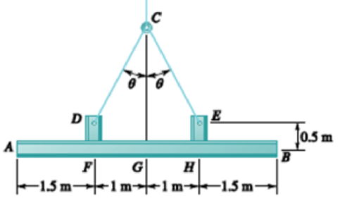
Solve Prob. 7.53 when θ = 60°.
PROBLEM 7.53 Two small channel sections DF and EH have been welded to the uniform beam AB of weight W = 3 kN to form the rigid structural member shown. This member is being lifted by two cables attached at D and E. Knowing that θ = 30° and neglecting the weight of the channel sections, (a) draw the shear and bending-moment diagrams for beam AB, (b) determine the maximum absolute values of the shear and bending moment in the beam.
Expert Solution & Answer
Want to see the full answer?
Check out a sample textbook solution
Students have asked these similar questions
(Read Question)
In figure A, the homogeneous rod of constant cross section is attached to unyielding supports. In figure B, a homogeneous bar with a cross-sectional area of 600 mm2 is attached to rigid supports. The bar carries the axial loads P1 = 20 kN and P2 = 60 kN, as shown.1. In figure A, derive the expression that calculates the reaction R1 in terms of P, and the given dimensions.2. In figure B, calculate the reaction (kN) at A.3. In figure B, calculate the maximum axial stress (MPa) in the rod.
(Read image)
Chapter 7 Solutions
Vector Mechanics for Engineers: Statics
Ch. 7.1 - 7.1 and 7.2 Determine the internal forces (axial...Ch. 7.1 - Prob. 7.2PCh. 7.1 - Determine the internal forces at point J when =...Ch. 7.1 - Fig. P7.3 and P7.4 7.4 Determine the internal...Ch. 7.1 - Determine the internal forces at point J when =...Ch. 7.1 - Fig. P7.5 and P7.6 7.6 Determine the internal...Ch. 7.1 - An archer aiming at a target is pulling with a...Ch. 7.1 - For the bow of Prob. 7.7, determine the magnitude...Ch. 7.1 - A semicircular rod is loaded as shown. Determine...Ch. 7.1 - A semicircular rod is loaded as shown. Determine...
Ch. 7.1 - A semicircular rod is loaded as shown. Determine...Ch. 7.1 - Fig. P7.11 and P7.12 7.12 A semicircular rod is...Ch. 7.1 - The axis of the curved member AB is a parabola...Ch. 7.1 - Knowing that the axis of the curved member AB is a...Ch. 7.1 - Knowing that the radius of each pulley is 120 mm...Ch. 7.1 - Fig. P7.15 and P7.16 7.16 Knowing that the radius...Ch. 7.1 - A 5-in.-diameter pipe is supported every 9 ft by a...Ch. 7.1 - For the frame of Prob. 7.17, determine the...Ch. 7.1 - Knowing that the radius of each pulley is 200 mm...Ch. 7.1 - Fig. P7.19 and P7.20 7.20 Knowing that the radius...Ch. 7.1 - and 7.22 A force P is applied to a bent rod that...Ch. 7.1 - and 7.22 A force P is applied to a bent rod that...Ch. 7.1 - A quarter-circular rod of weight W and uniform...Ch. 7.1 - For the rod of Prob. 7.23, determine the magnitude...Ch. 7.1 - A semicircular rod of weight W and uniform cross...Ch. 7.1 - A semicircular rod of weight W and uniform cross...Ch. 7.1 - 7.27 and 7.28 A half section of pipe rests on a...Ch. 7.1 - 7.27 and 7.28 A half section of pipe rests on a...Ch. 7.2 - 7.29 through 7.32 For the beam and loading shown,...Ch. 7.2 - 7.29 through 7.32 For the beam and loading shown,...Ch. 7.2 - 7.29 through 7.32 For the beam and loading shown,...Ch. 7.2 - 7.29 through 7.32 For the beam and loading shown,...Ch. 7.2 - 7.33 and 7.34 For the beam and loading shown, (a)...Ch. 7.2 - 7.33 and 7.34 For the beam and loading shown, (a)...Ch. 7.2 - 7.35 and 7.36 For the beam and loading shown, (a)...Ch. 7.2 - 7.35 and 7.36 For the beam and loading shown, (a)...Ch. 7.2 - 7.37 and 7.38 For the beam and loading shown, (a)...Ch. 7.2 - 7.37 and 7.38 For the beam and loading shown, (a)...Ch. 7.2 - For the beam and loading shown, (a) draw the shear...Ch. 7.2 - For the beam and loading shown, (a) draw the shear...Ch. 7.2 - For the beam and loading shown, (a) draw the shear...Ch. 7.2 - For the beam and loading shown, (a) draw the shear...Ch. 7.2 - Assuming the upward reaction of the ground on beam...Ch. 7.2 - Solve Problem 7.43 knowing that P = 3wa. PROBLEM...Ch. 7.2 - Assuming the upward reaction of the ground on beam...Ch. 7.2 - Solve Prob. 7.45 assuming that the 12-kip load has...Ch. 7.2 - Assuming the upward reaction of the ground on beam...Ch. 7.2 - Prob. 7.48PCh. 7.2 - Draw the shear and bending-moment diagrams for the...Ch. 7.2 - Draw the shear and bending-moment diagrams for the...Ch. 7.2 - Draw the shear and bending-moment diagrams for the...Ch. 7.2 - Draw the shear and bending-moment diagrams for the...Ch. 7.2 - Two small channel sections DF and EH have been...Ch. 7.2 - Solve Prob. 7.53 when = 60. PROBLEM 7.53 Two...Ch. 7.2 - For the structural member of Prob. 7.53, determine...Ch. 7.2 - For the beam of Prob. 7.43, determine (a) the...Ch. 7.2 - Determine (a) the distance a for which the maximum...Ch. 7.2 - For the beam and loading shown, determine (a) the...Ch. 7.2 - A uniform beam is to be picked up by crane cables...Ch. 7.2 - Knowing that P = Q = 150 lb, determine (a) the...Ch. 7.2 - Knowing that P = Q = 150 lb, determine (a) the...Ch. 7.2 - In order to reduce the bending moment in the...Ch. 7.3 - Using the method of Sec. 7.3, solve Prob. 7.29....Ch. 7.3 - Prob. 7.64PCh. 7.3 - Using the method of Sec. 7.3, solve Prob. 7.31....Ch. 7.3 - Prob. 7.66PCh. 7.3 - Using the method of Sec. 7.3, solve Prob. 7.33....Ch. 7.3 - Using the method of Sec. 7.3, solve Prob. 7.34....Ch. 7.3 - 7.69 and 7.70 For the beam and loading shown, (a)...Ch. 7.3 - 7.69 and 7.70 For the beam and loading shown, (a)...Ch. 7.3 - Using the method of Sec. 7.3, solve Prob. 7.39....Ch. 7.3 - Using the method of Sec. 7.3, solve Prob. 7.40....Ch. 7.3 - Using the method of Sec. 7.3, solve Prob. 7.41....Ch. 7.3 - Using the method of Sec. 7.3, solve Prob. 7.42....Ch. 7.3 - 7.75 and 7.76 For the beam and loading shown, (a)...Ch. 7.3 - Prob. 7.76PCh. 7.3 - For the beam and loading shown, (a) draw the shear...Ch. 7.3 - For the beam and loading shown, (a) draw the shear...Ch. 7.3 - For the beam and loading shown, (a) draw the shear...Ch. 7.3 - For the beam and loading shown, (a) draw the shear...Ch. 7.3 - For the beam and loading shown, (a) draw the shear...Ch. 7.3 - For the beam and loading shown, (a) draw the shear...Ch. 7.3 - (a) Draw the shear and bending-moment diagrams for...Ch. 7.3 - Solve Prob. 7.83 assuming that the 300-lb force...Ch. 7.3 - For the beam and loading shown, (a) write the...Ch. 7.3 - For the beam and loading shown, (a) write the...Ch. 7.3 - For the beam and loading shown, (a) write the...Ch. 7.3 - For the beam and loading shown, (a) write the...Ch. 7.3 - The beam AB supports the uniformly distributed...Ch. 7.3 - Solve Prob. 7.89 assuming that the uniformly...Ch. 7.3 - The beam AB is subjected to the uniformly...Ch. 7.3 - Prob. 7.92PCh. 7.4 - Three loads are suspended as shown from the cable...Ch. 7.4 - Knowing that the maximum tension in cable ABCDE is...Ch. 7.4 - If dA = 8 ft and dc = 10 ft, determine the...Ch. 7.4 - Prob. 7.96PCh. 7.4 - Knowing that dc = 5 m, determine (a) the distances...Ch. 7.4 - Prob. 7.98PCh. 7.4 - Knowing that dc = 9 ft, determine (a) the...Ch. 7.4 - Prob. 7.100PCh. 7.4 - Knowing that mB = 70 kg and mC = 25 kg, determine...Ch. 7.4 - Fig. P7.101 and P7.102 7.102 Knowing that mB = 18...Ch. 7.4 - Cable ABC supports two loads as shown. Knowing...Ch. 7.4 - Prob. 7.104PCh. 7.4 - If a = 3 m, determine the magnitudes of P and Q...Ch. 7.4 - If a = 4 m, determine the magnitudes of P and Q...Ch. 7.4 - An electric wire having a mass per unit length of...Ch. 7.4 - The total mass of cable ACB is 20 kg. Assuming...Ch. 7.4 - The center span of the George Washington Bridge,...Ch. 7.4 - The center span of the Verrazano-Narrows Bridge...Ch. 7.4 - Each cable of the Golden Gate Bridge supports a...Ch. 7.4 - Two cables of the same gauge are attached to a...Ch. 7.4 - A 76-m length of wire having a mass per unit...Ch. 7.4 - A cable of length L + is suspended between two...Ch. 7.4 - The total mass of cable AC is 25 kg. Assuming that...Ch. 7.4 - Cable ACB supports a load uniformly distributed...Ch. 7.4 - Each cable of the side spans of the Golden Gate...Ch. 7.4 - A steam pipe weighing 45 lb/ft that passes between...Ch. 7.4 - A cable AB of span L and a simple beam AB of the...Ch. 7.4 - Making use of the property established in Prob....Ch. 7.4 - 7.120 through 7.123 Making use of the property...Ch. 7.4 - 7.120 through 7.123 Making use of the property...Ch. 7.4 - Prob. 7.123PCh. 7.4 - Prob. 7.124PCh. 7.4 - Using the property indicated in Prob. 7.124,...Ch. 7.4 - If the weight per unit length of the cable AB is...Ch. 7.5 - A 25-ft chain with a weight of 30 lb is suspended...Ch. 7.5 - A 500-ft-long aerial tramway cable having a weight...Ch. 7.5 - A 40-m cable is strung as shown between two...Ch. 7.5 - A 50-m steel surveying tape has a mass of 1.6 kg....Ch. 7.5 - Prob. 7.131PCh. 7.5 - Prob. 7.132PCh. 7.5 - A 20-m length of wire having a mass per unit...Ch. 7.5 - Determine the sag of a 30-ft chain that is...Ch. 7.5 - Prob. 7.135PCh. 7.5 - Prob. 7.136PCh. 7.5 - A cable weighing 2 lb/ft is suspended between two...Ch. 7.5 - Prob. 7.138PCh. 7.5 - Prob. 7.139PCh. 7.5 - Fig. P7.139 and P7.140 7.140 A motor M is used to...Ch. 7.5 - Prob. 7.141PCh. 7.5 - Prob. 7.142PCh. 7.5 - Prob. 7.143PCh. 7.5 - Prob. 7.144PCh. 7.5 - To the left of point B, the long cable ABDE rests...Ch. 7.5 - Fig. P7.145 and P7.146 7.146 To the left of point...Ch. 7.5 - The 10-ft cable AB is attached to two collars as...Ch. 7.5 - Prob. 7.148PCh. 7.5 - Prob. 7.149PCh. 7.5 - (a) Determine the maximum allowable horizontal...Ch. 7.5 - A cable has a mass per unit length of 3 kg/m and...Ch. 7.5 - Determine the sag-to-span ratio for which the...Ch. 7.5 - Prob. 7.153PCh. 7 - Knowing that the turnbuckle has been tightened...Ch. 7 - Knowing that the turnbuckle has been tightened...Ch. 7 - Two members, each consisting of a straight and a...Ch. 7 - Knowing that the radius of each pulley is 150 mm,...Ch. 7 - For the beam shown, determine (a) the magnitude P...Ch. 7 - For the beam and loading shown, (a) draw the shear...Ch. 7 - For the beam and loading shown, (a) draw the shear...Ch. 7 - For the beam shown, draw the shear and...Ch. 7 - The beam AB, which lies on the ground, supports...Ch. 7 - Two loads are suspended as shown from the cable...Ch. 7 - A wire having a mass per unit length of 0.65 kg/m...Ch. 7 - A 10-ft rope is attached to two supports A and B...
Knowledge Booster


Learn more about
Need a deep-dive on the concept behind this application? Look no further. Learn more about this topic, mechanical-engineering and related others by exploring similar questions and additional content below.Similar questions
- (Read Image)arrow_forwardM16x2 grade 8.8 bolts No. 25 C1- Q.2. The figure is a cross section of a grade 25 cast-iron pressure vessel. A total of N, M16x2.0 grade 8.8 bolts are to be used to resist a separating force of 160 kN. (a) Determine ks, km, and C. (b) Find the number of bolts required for a load factor of 2 where the bolts may be reused when the joint 19 mm is taken apart. (c) with the number of bolts obtained in (b), determine the realized load factor for overload, the yielding factor of safety, and the separation factor of safety. 19 mmarrow_forwardProblem4. The thin uniform disk of mass m = 1-kg and radius R = 0.1m spins about the bent shaft OG with the angular speed w2 = 20 rad/s. At the same time, the shaft rotates about the z-axis with the angular speed 001 = 10 rad/s. The angle between the bent portion of the shaft and the z-axis is ẞ = 35°. The mass of the shaft is negligible compared to the mass of the disk. a. Find the angular momentum of the disk with respect to point G, based on the axis orientation as shown. Include an MVD in your solution. b. Find the angular momentum of the disk with respect to point O, based on the axis orientation as shown. (Note: O is NOT the center of fixed-point rotation.) c. Find the kinetic energy of the assembly. z R R 002 2R x Answer: H = -0.046ĵ-0.040 kg-m²/sec Ho=-0.146-0.015 kg-m²/sec T 0.518 N-m =arrow_forward
- Problem 3. The assembly shown consists of a solid sphere of mass m and the uniform slender rod of the same mass, both of which are welded to the shaft. The assembly is rotating with angular velocity w at a particular moment. Find the angular momentum with respect to point O, in terms of the axes shown. Answer: Ñ。 = ½mc²wcosßsinßĵ + (}{mr²w + 2mb²w + ½ mc²wcos²ß) k 3 m r b 2 C لا marrow_forwardOnly question 2arrow_forwardOnly question 1arrow_forward
- Only question 3arrow_forwardI have Euler parameters that describe the orientation of N relative to Q, e = -0.7071*n3, e4 = 0.7071. I have Euler parameters that describe the orientation of U relative to N, e = -1/sqrt(3)*n1, e4 = sqrt(2/3). After using euler parameter rule of successive rotations, I get euler parameters that describe the orientation of U relative to Q, e = -0.4082*n1 - 0.4082*n2 - 0.5774*n3. I need euler parameters that describe the orientation of U relative to Q in vector basis of q instead of n. How do I get that?arrow_forwardDescribe at least 4 processes in engineering where control charts are (or should be) appliedarrow_forward
- Describe at least two (2) processes where control charts are (or should be) applied.arrow_forwardProblem 3: A cube-shaped spacecraft is in a circular Earth orbit. Let N (n,) be inertial and the spacecraft is denoted S (ŝ₁). The spacecraft is described such that ¯½º = J ŝ₁ŝ₁ + J ŝ₂§₂ + J §¸Ŝ3 Location of the spacecraft in the orbit is determined by the orbit-fixed unit vectors ê, that are oriented by the angle (Qt), where is a constant angular rate. 52 €3 3> 2t 55 Λ Из At the instant when Qt = 90°, the spacecraft S is oriented relative to the orbit such that 8₁ = 0° Space-three 1-2-3 angles 0₂ = 60° and ES = $₂ rad/s 0₁ = 135° (a) At this instant, determine the direction cosine matrix that describes the orientation of the spacecraft with respect to the inertial frame N.arrow_forwardThis problem illustrates that the factor of safety for a machine element depends on the particular point selected for analysis. Here you are to compute factors of safety, based upon the distortion-energy theory, for stress elements at A and B of the member shown in the figure. This bar is made of AISI 1006 cold-drawn steel and is loaded by the forces F = 1.100 kN, P = 8.00 kN, and T = 50.00 N-m. Given: Sy = 280 MPa. B -100 mm- 15-mm D. a) Determine the value of the axial stress at point B. b) Determine the value of the shear stress at point B. c) Determine the value of the Von Mises stress at point B. P Farrow_forward
arrow_back_ios
SEE MORE QUESTIONS
arrow_forward_ios
Recommended textbooks for you
 Elements Of ElectromagneticsMechanical EngineeringISBN:9780190698614Author:Sadiku, Matthew N. O.Publisher:Oxford University Press
 Mechanics of Materials (10th Edition)Mechanical EngineeringISBN:9780134319650Author:Russell C. HibbelerPublisher:PEARSON
 Thermodynamics: An Engineering ApproachMechanical EngineeringISBN:9781259822674Author:Yunus A. Cengel Dr., Michael A. BolesPublisher:McGraw-Hill Education
 Control Systems EngineeringMechanical EngineeringISBN:9781118170519Author:Norman S. NisePublisher:WILEY
 Mechanics of Materials (MindTap Course List)Mechanical EngineeringISBN:9781337093347Author:Barry J. Goodno, James M. GerePublisher:Cengage Learning
 Engineering Mechanics: StaticsMechanical EngineeringISBN:9781118807330Author:James L. Meriam, L. G. Kraige, J. N. BoltonPublisher:WILEY
Elements Of Electromagnetics
Mechanical Engineering
ISBN:9780190698614
Author:Sadiku, Matthew N. O.
Publisher:Oxford University Press
Mechanics of Materials (10th Edition)
Mechanical Engineering
ISBN:9780134319650
Author:Russell C. Hibbeler
Publisher:PEARSON
Thermodynamics: An Engineering Approach
Mechanical Engineering
ISBN:9781259822674
Author:Yunus A. Cengel Dr., Michael A. Boles
Publisher:McGraw-Hill Education
Control Systems Engineering
Mechanical Engineering
ISBN:9781118170519
Author:Norman S. Nise
Publisher:WILEY
Mechanics of Materials (MindTap Course List)
Mechanical Engineering
ISBN:9781337093347
Author:Barry J. Goodno, James M. Gere
Publisher:Cengage Learning
Engineering Mechanics: Statics
Mechanical Engineering
ISBN:9781118807330
Author:James L. Meriam, L. G. Kraige, J. N. Bolton
Publisher:WILEY
Everything About COMBINED LOADING in 10 Minutes! Mechanics of Materials; Author: Less Boring Lectures;https://www.youtube.com/watch?v=N-PlI900hSg;License: Standard youtube license