
Concept explainers
Videos
7.35 and 7.36 For the beam and loading shown, (a) draw the shear and bending-moment diagrams, (b) determine the maximum absolute values of the shear and bending moment.
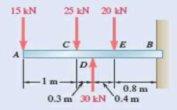
Fig. P7.35
(a)
The shear and bending-moment diagrams.
Answer to Problem 7.35P
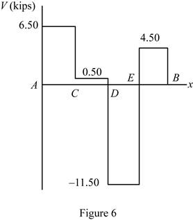
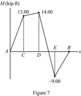
The shear diagram is drawn in figure 6 and bending momentum is drawn in figure 7.
Explanation of Solution
Refer Figure 1.
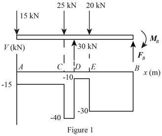
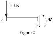
Refer Figure 2.
Write an expression to calculate the net counter clockwise moment at point C along AC.
Here,
Write an expression to calculate the net vertical force along AC.
Here,
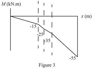
Refer Figure 3.
Write an expression to calculate the net counter clockwise moment at point D along CD.
Here,
Write an expression to calculate the net vertical force along CD.
Refer Figure 4.
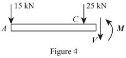
Write an expression to calculate the net counter clockwise moment at point E along DE.
Here,
Write an expression to calculate the net vertical force along EB.
Refer Figure 5.
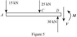
Write an expression to calculate the net counter clockwise moment at point B along EB.
Here,
Write an expression to calculate the net vertical force along EB.
Conclusion:
Refer Figure 2 and equation (II). Calculate the net vertical force.
Here,
Rearrange the equation to calculate
Refer Figure 2 and equation (I). Calculate the net counter clockwise moment at point C.
Here,
Rearrange the equation to calculate
Refer Figure 3 and equation (IV). Calculate the net vertical force.
Rearrange the equation to calculate
Refer Figure 3 and equation (III). Calculate the net counter clockwise moment at point D.
Rearrange the equation to calculate
Refer Figure 4 and equation (VI). Calculate the net vertical force.
Rearrange the equation to calculate
Refer Figure 4 and equation (V). Calculate the net counter clockwise moment at point E.
Rearrange the equation to calculate
Refer Figure 5 and equation (VIII). Calculate the net vertical force.
Rearrange the equation to calculate
Refer Figure 5 and equation (VII). Calculate the net counter clockwise moment at point E.
Rearrange the equation to calculate
Thus, draw the shear diagram.
Thus, draw the bending-moment.
(b)
The maximum absolute value of the shear and bending moment.
Answer to Problem 7.35P
The maximum absolute value of the shear force is
Explanation of Solution
Determine the maximum absolute shear from diagram 2. The maximum absolute value of bending moment is at maximum shear force.
Conclusion:
Refer figure 6. Determine the maximum absolute value of shear force.
Here,
Refer figure 7. Determine the maximum value of the bending moment at position B.
Here,
Thus, the maximum absolute value of the shear force is
Want to see more full solutions like this?
Chapter 7 Solutions
VEC MECH 180-DAT EBOOK ACCESS(STAT+DYNA)


- Sketch and describe how ships are supported in dry dock. When and where does the greatest amount of stresses occur?arrow_forwardSketch and desribe a balanced rudder and how it is suspendedarrow_forwardA ship 140 m long and 18 m beam floats at a draught of9 m. The immersed cross-sectionai areas at equai intervais are 5,60, 116, 145, 152, 153, 153, 151, 142, 85 and 0 m2 respectively.Calculate:(a) displacement(b) block coefficient(c) midship section area coefficient(d) prismatic coefficient.arrow_forward
- A steamer has waterplane area 1680m2 recorded in water with relative denisty 1.013. Displacement = 1200 t, calculate difference in draught in salwater reltive denisity 1.025.arrow_forwardrelative velocity 11.72 m/s is correct, need help finding the angle pleasearrow_forwardDetermine the distance between the two automobiles 2 s after A has passed through the intersection.arrow_forward
- A box barge 65 m long and 12 m wide floats at a draught of5.5 m in sea water. Calculate:(a) the displacement of the barge,(b) its draught in fresh waterarrow_forwardwhat is the angle of the velocity of block B? velocity is 7.46 in/s Determine the acceleration and angle of block B. (Round the acceleration value to three decimal places.)arrow_forwardDetermine the relative velocity of B with respect to A.arrow_forward
- Generate the kinematic diagram of the following mechanism. Then, draw their graphs and calculate their degrees of freedom (DoF) using Gruebler's formula.arrow_forwardAn elastic bar of length L = 1m and cross section A = 1cm2 spins with angular velocity ω about an axis, as shown in the figure below. The radial acceleration at a generic point x along the bar is a(x) = ω2x, where ω= 100rad/s is the angular velocity. The bar is pinned on the rotation axis at x = 0. A mass M = 1kg is attached to the right end of the bar. Due to the radial acceleration, the bar stretches along x with displacement function u(x). The displacement u(x) solves the BVP (strong form) sketched below: d dx (σ(x)) + ρa(x) = 0 PDE σ(x) = E du dx Hooke’s law (1) u(0) =?? essential BC σ(L) =?? natural BC where σ(x) is the axial stress in the rod, ρ= 2700kg /m3 is the mass density, and E = 70GPa is the Young’s modulus 1. Define appropriate BCs for the strong BVP 2. Find the solution of the strong BVP analytically 3. Derive the weak form of the BVP.arrow_forwardGruebler's formula for the following mechanism?arrow_forward
 Elements Of ElectromagneticsMechanical EngineeringISBN:9780190698614Author:Sadiku, Matthew N. O.Publisher:Oxford University Press
 Mechanics of Materials (10th Edition)Mechanical EngineeringISBN:9780134319650Author:Russell C. HibbelerPublisher:PEARSON
 Thermodynamics: An Engineering ApproachMechanical EngineeringISBN:9781259822674Author:Yunus A. Cengel Dr., Michael A. BolesPublisher:McGraw-Hill Education
 Control Systems EngineeringMechanical EngineeringISBN:9781118170519Author:Norman S. NisePublisher:WILEY
 Mechanics of Materials (MindTap Course List)Mechanical EngineeringISBN:9781337093347Author:Barry J. Goodno, James M. GerePublisher:Cengage Learning
 Engineering Mechanics: StaticsMechanical EngineeringISBN:9781118807330Author:James L. Meriam, L. G. Kraige, J. N. BoltonPublisher:WILEY