
Concept explainers
Videos
Knowing that dc = 9 ft, determine (a) the distances dB and dD (b) the reaction at E.
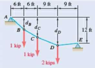
Fig. P7.99 and P7.100
(a)
The distances
Answer to Problem 7.99P
The distance
Explanation of Solution
Refer Fig P7.99.
The figure 1 below shows the free body diagram of the portion ABC.
The total moment about the point C is zero.
Refer the free body diagram and write the equation for the moment about point C.
Here
Re-write the above equation to get an expression for
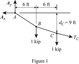
The figure 2 below shows the free body diagram of the entire cable.
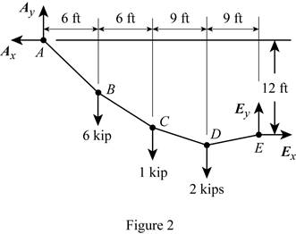
The moment about point E is zero.
Refer the free body diagram of the entire cable and write the equation of the moment about point E.
Simplify the above equation.
Since the system is in equilibrium the total vertical and horizontal components will be zero.
Refer figure 2 and write the equation for total horizontal force.
Here
Refer figure 2 and write the equation for the total vertical force.
The figure 4 below shows the free body diagram of the portion AB.
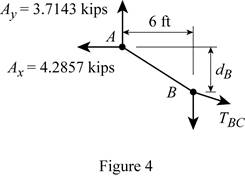
The moment about point B is zero.
Refer figure 4 and write the equation for the moment about point B.
The figure 5 below shows the free body diagram of the portion DE.
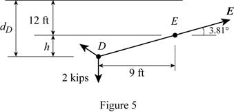
Refer figure 5 and write the formula for the distance
Here
Refer figure 5 and write the formula for distance
Conclusion:
Substitute equation (I) in equation (II).
Substitute
Substitute
Substitute
Substitute
Calculate
Substitute
The distance
(b)
The reaction at point E.
Answer to Problem 7.99P
The reaction at point E is
Explanation of Solution
Refer Fig P7.99.
The figure 1 below shows the free body diagram of the portion ABC.
The total moment about the point C is zero.
Refer the free body diagram and write the equation for the moment about point C.
Here
Re-write the above equation to get an expression for
The figure 2 below shows the free body diagram of the entire cable.
The moment about point E is zero.
Refer the free body diagram of the entire cable and write the equation of the moment about point E.
Simplify the above equation.
Since the system is in equilibrium the total vertical and horizontal components will be zero.
Refer figure 2 and write the equation for total horizontal force.
Here
Refer figure 2 and write the equation for the total vertical force.
Write the formula for the magnitude of the reaction at point E.
Here
Write the formula for the angle made by the reaction at point E with horizontal.
Here
Conclusion:
Substitute equation (I) in equation (II).
Substitute
Substitute
Substitute
Substitute
Substitute
Thus the reaction at point E is
Want to see more full solutions like this?
Chapter 7 Solutions
VEC MECH 180-DAT EBOOK ACCESS(STAT+DYNA)


- Determine the force in each member of the space truss given F=5 kN. Use positive to indicate tension and negative to indicate compression. F E Z -2 m. B 3 m C 5 m 3 m A -4 m. AB = KN FAC = FAD = KN KN KN FBC = KN FBD FBE = = KN Farrow_forwardA short brass cyclinder (denisty=8530 kg/m^3, cp=0.389 kJ/kgK, k=110 W/mK, and alpha=3.39*10^-5 m^2/s) of diameter 4 cm and height 20 cm is initially at uniform temperature of 150 degrees C. The cylinder is now placed in atmospheric air at 20 degrees C, where heat transfer takes place by convection with a heat transfer coefficent of 40 W/m^2K. Calculate (a) the center temp of the cylinder, (b) the center temp of the top surface of the cylinder, and (c) the total heat transfer from the cylinder 15 min after the start of the cooling. Solve this problem using the analytical one term approximation method. (Answer: (a) 45.7C, (b)45.3C, (c)87.2 kJ)arrow_forwardA short brass cyclinder (denisty=8530 kg/m^3, cp=0.389 kJ/kgK, k=110 W/mK, and alpha=3.39*10^-5 m^2/s) of diameter 4 cm and height 20 cm is initially at uniform temperature of 150 degrees C. The cylinder is now placed in atmospheric air at 20 degrees C, where heat transfer takes place by convection with a heat transfer coefficent of 40 W/m^2K. Calculate (a) the center temp of the cylinder, (b) the center temp of the top surface of the cylinder, and (c) the total heat transfer from the cylinder 15 min after the start of the cooling. Solve this problem using the analytical one term approximation method.arrow_forward
- A 6 cm high rectangular ice block (k=2.22 W/mK, and alpha=0.124*10^-7 m^2/s) initially at -18 degrees C is placed on a table on its square base 4 cm by 4cm in size in a room at 18 degrees C. The heat transfer coefficent on the exposed surfaces of the ice block is 12 W/m^2K. Disregarding any heat transfer from the base to the table, determine how long it will be before the ice block starts melting. Where on the ice block will the first liquid droplets appear? Solve this problem using the analytical one-term approximation method.arrow_forwardConsider a piece of steel undergoing a decarburization process at 925 degrees C. the mass diffusivity of carbon in steel at 925 degrees C is 1*10^-7 cm^2/s. Determine the depth below the surface of the steel at which the concentration of carbon is reduced to 40 percent from its initial value as a result of the decarburization process for (a) an hour and (b) 10 hours. Assume the concnetration of carbon at the surface is zero throughout the decarburization process.arrow_forwardPlease do not rely too much on chatgpt, because its answer may be wrong. Please consider it carefully and give your own answer. You can borrow ideas from gpt, but please do not believe its answer.Very very grateful! Please do not copy other's work,i will be very very grateful!!arrow_forward
- Multiple Choice Circle the best answer to each statement. 1. Which geometry attribute deviation(s) can be limited with a profile of a surface tolerance? A. Location B. Orientation C. Form D. All of the above 2. A true profile may be defined with: A. Basic radii B. Basic angles C. Formulas D. All of the above 3. Which modifier may be applied to the profile tolerance value? A B C. D. All of the above 4. The default tolerance zone for a profile tolerance is: A. Non-uniform B. Unilateral C. Bilateral equal distribution D. Bilateral-unequal distribution 5. An advantage of using a profile tolerance in place of a coordinate tolerance is: A. A bonus tolerance is permitted. B. A datum feature sequence may be specified C. A profile tolerance always controls size D. All of the above 6. The shape of the tolerance zone for a profile tolerance is: A. Two parallel planes B. The same as the true profile of the toleranced surface C. Equal bilateral D. Cylindrical when the diameter symbol is speci- fied…arrow_forwardOne thousand kg/h of a (50-50 wt%) acetone-in-water solution is to be extracted at 25C in a continuous, countercurrent system with pure 1,1,2-trichloroethane to obtain a raffinate containing 10 wt% acetone. Using the following equilibrium data, determine with an equilateral-triangle diagram: a- the minimum flow rate of solvent; b- the number of stages required for a solvent rate equal to 1.5 times minimum, and composition of each streamleaving each stage. c- Repeat the calculation of (a) and (b) if the solvent used has purity 93wt% (4wr% acetone, 3wt% water impurities) acetone water 1,1,2-trichloroethane Raffinate. Weight Extract. Weight 0.6 0.13 0.27 Fraction Acetone Fraction Acetone 0.5 0.04 0.46 0.44 0.56 0.4 0.03 0.57 0.29 0.40 0.3 0.02 0.68 0.12 0.18 0.2 0.015 0.785 0.0 0.0 0.1 0.01 0.89 0.55 0.35 0.1 0.5 0.43 0.07 0.4 0.57 0.03 0.3 0.68 0.02 0.2 0.79 0.01 0.1 0.895 0.005arrow_forward2500 kg/hr of (20-80) nicotine water solution is to be extracted with benzene containing 0.5% nicotine in the 1st and 2ed stages while the 3rd stage is free of nicotine. Cross- current operation is used with different amounts of solvent for each stages 2000kg/hr in the 1st stage, 2300 kg/hr in the 2nd stage, 2600 kg/hr in the 3rd, determine: - a- The final raffinate concentration and % extraction. b- b- The minimum amount of solvent required for counter-current operation if the minimum concentration will be reduced to 5% in the outlet raffinate. Equilibrium data Wt % Nicotine in water Wt % Nicotine in benzene 0 4 16 25 0 4 21 30arrow_forward
- Quiz/An eccentrically loaded bracket is welded to the support as shown in Figure below. The load is static. The weld size for weld w1 is h1=6mm, for w2 h2 5mm, and for w3 is h3 -5.5 mm. Determine the safety factor (S.f) for the welds. F=22 kN. Use an AWS Electrode type (E90xx). 140 101.15 REDMI NOTE 8 PRO AI QUAD CAMERA Farrow_forward(read image)arrow_forwardProblem 3.30 A piston-cylinder device contains 0.85 kg of refrigerant- 134a at -10°C. The piston that is free to move has a mass of 12 kg and a diameter of 25 cm. The local atmospheric pressure is 100 kPa. Now, heat is transferred to refrigerant-134a until the temperature is 15°C. Determine (a) the final pressure, (b) the change in the volume of the refrigerant, and (c) the change in the enthalpy of the refrigerant-134a. please show Al work step by steparrow_forward
 Elements Of ElectromagneticsMechanical EngineeringISBN:9780190698614Author:Sadiku, Matthew N. O.Publisher:Oxford University Press
 Mechanics of Materials (10th Edition)Mechanical EngineeringISBN:9780134319650Author:Russell C. HibbelerPublisher:PEARSON
 Thermodynamics: An Engineering ApproachMechanical EngineeringISBN:9781259822674Author:Yunus A. Cengel Dr., Michael A. BolesPublisher:McGraw-Hill Education
 Control Systems EngineeringMechanical EngineeringISBN:9781118170519Author:Norman S. NisePublisher:WILEY
 Mechanics of Materials (MindTap Course List)Mechanical EngineeringISBN:9781337093347Author:Barry J. Goodno, James M. GerePublisher:Cengage Learning
 Engineering Mechanics: StaticsMechanical EngineeringISBN:9781118807330Author:James L. Meriam, L. G. Kraige, J. N. BoltonPublisher:WILEY