
Concept explainers
Videos
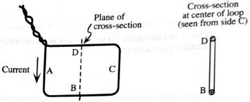
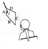
A wire is formed into a and the leads are twisted together. The sides of the loop are labeled A—D. The direction of the current is shown. (The diagram uses the convention that
1. On the top two diagrams at right, sketch magnetic field lines for the loop. Base your answer on your knowledge of the magnetic field of a current-carrying wire.
Explain why it is reasonable to ignore the effect of the magnetic field from the wire leads.
2. Consider the magnetic field of a bar magnet.
How are the magnetic field lines for the current loop similar to those for a short barmagnet?
Can you identify a “north” and a “south” pole for a current loop?
Devise a rule by which you can use your right hand to identify the magnetic poles of the loop from your knowledge of the direction of the current.
Want to see the full answer?
Check out a sample textbook solution
Chapter 7 Solutions
Tutorials in Introductory Physics
Additional Science Textbook Solutions
Microbiology: An Introduction
Microbiology: An Introduction
Chemistry: An Introduction to General, Organic, and Biological Chemistry (13th Edition)
Organic Chemistry (8th Edition)
Cosmic Perspective Fundamentals
College Physics: A Strategic Approach (3rd Edition)


- Use the following information to answer the next two questions. A laser is directed at a prism made of zircon (n = 1.92) at an incident angle of 35.0°, as shown in the diagram. 3a) Determine the critical angle of zircon. 35.0° 70° 55 55° 3b) Determine the angle of refraction when the laser beam leaves the prism.arrow_forwardNo chatgpt pls will upvotearrow_forwardA beam of alpha-particles of energy 7.3MeV is used.The protons emitted at an angle of zero degree are found to have energy of 9.34MeV.Find the Q-value of this reaction .arrow_forward
- An aluminum rod and a copper rod have the same length of 100cm at 5C. At what temperatures would one of the rods be 0.5 mm longer than the other? Which rod is longer at such temperature?arrow_forwardROTATIONAL DYNAMICS Question 01 A solid circular cylinder and a solid spherical ball of the same mass and radius are rolling together down the same inclined. Calculate the ratio of their kinetic energy. Assume pure rolling motion Question 02 A sphere and cylinder of the same mass and radius start from ret at the same point and more down the same plane inclined at 30° to the horizontal Which body gets the bottom first and what is its acceleration b) What angle of inclination of the plane is needed to give the slower body the same acceleration Question 03 i) Define the angular velocity of a rotating body and give its SI unit A car wheel has its angular velocity changing from 2rads to 30 rads seconds. If the radius of the wheel is 400mm. calculate ii) The angular acceleration iii) The tangential linear acceleration of a point on the rim of the wheel Question 04 in 20arrow_forwardQuestion B3 Consider the following FLRW spacetime: t2 ds² = -dt² + (dx² + dy²+ dz²), t2 where t is a constant. a) State whether this universe is spatially open, closed or flat. [2 marks] b) Determine the Hubble factor H(t), and represent it in a (roughly drawn) plot as a function of time t, starting at t = 0. [3 marks] c) Taking galaxy A to be located at (x, y, z) = (0,0,0), determine the proper distance to galaxy B located at (x, y, z) = (L, 0, 0). Determine the recessional velocity of galaxy B with respect to galaxy A. d) The Friedmann equations are 2 k 8πG а 4πG + a² (p+3p). 3 a 3 [5 marks] Use these equations to determine the energy density p(t) and the pressure p(t) for the FLRW spacetime specified at the top of the page. [5 marks] e) Given the result of question B3.d, state whether the FLRW universe in question is (i) radiation-dominated, (ii) matter-dominated, (iii) cosmological-constant-dominated, or (iv) none of the previous. Justify your answer. f) [5 marks] A conformally…arrow_forward
- SECTION B Answer ONLY TWO questions in Section B [Expect to use one single-sided A4 page for each Section-B sub question.] Question B1 Consider the line element where w is a constant. ds²=-dt²+e2wt dx², a) Determine the components of the metric and of the inverse metric. [2 marks] b) Determine the Christoffel symbols. [See the Appendix of this document.] [10 marks] c) Write down the geodesic equations. [5 marks] d) Show that e2wt it is a constant of geodesic motion. [4 marks] e) Solve the geodesic equations for null geodesics. [4 marks]arrow_forwardPage 2 SECTION A Answer ALL questions in Section A [Expect to use one single-sided A4 page for each Section-A sub question.] Question A1 SPA6308 (2024) Consider Minkowski spacetime in Cartesian coordinates th = (t, x, y, z), such that ds² = dt² + dx² + dy² + dz². (a) Consider the vector with components V" = (1,-1,0,0). Determine V and V. V. (b) Consider now the coordinate system x' (u, v, y, z) such that u =t-x, v=t+x. [2 marks] Write down the line element, the metric, the Christoffel symbols and the Riemann curvature tensor in the new coordinates. [See the Appendix of this document.] [5 marks] (c) Determine V", that is, write the object in question A1.a in the coordinate system x'. Verify explicitly that V. V is invariant under the coordinate transformation. Question A2 [5 marks] Suppose that A, is a covector field, and consider the object Fv=AAμ. (a) Show explicitly that F is a tensor, that is, show that it transforms appropriately under a coordinate transformation. [5 marks] (b)…arrow_forwardHow does boiling point of water decreases as the altitude increases?arrow_forward
 Physics for Scientists and Engineers: Foundations...PhysicsISBN:9781133939146Author:Katz, Debora M.Publisher:Cengage Learning
 Physics for Scientists and EngineersPhysicsISBN:9781337553278Author:Raymond A. Serway, John W. JewettPublisher:Cengage Learning
 Physics for Scientists and Engineers with Modern ...PhysicsISBN:9781337553292Author:Raymond A. Serway, John W. JewettPublisher:Cengage Learning
 Glencoe Physics: Principles and Problems, Student...PhysicsISBN:9780078807213Author:Paul W. ZitzewitzPublisher:Glencoe/McGraw-Hill
 Physics for Scientists and Engineers, Technology ...PhysicsISBN:9781305116399Author:Raymond A. Serway, John W. JewettPublisher:Cengage Learning