
Concept explainers
Videos
- (a) Water flows through a shower head steadily at a rate of 10 L/min. An electric resistance heater placed in the water pipe heats the water from 16 to 43°C. Taking the density of water to be 1 kg/L, determine the electric power input to the heater in kW and the rate of entropy generation during this process in kW/K.
FIGURE P7–209
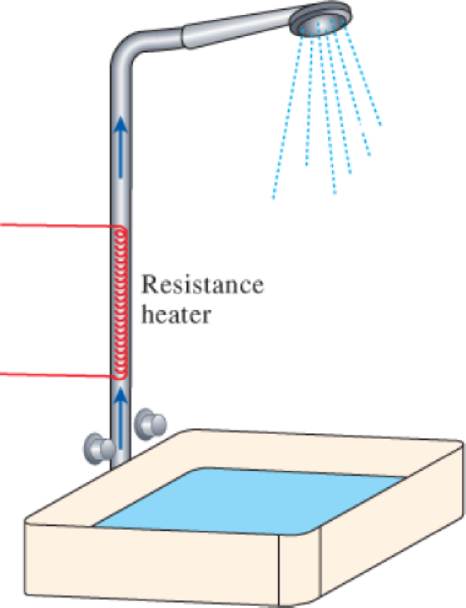
- (b) In an effort to conserve energy, it is proposed to pass the drained warm water at a temperature of 39°C through a heat exchanger to preheat the incoming cold water. If the heat exchanger has an effectiveness of 0.50 (that is, it recovers only half of the energy that can possibly be transferred from the drained water to incoming cold water), determine the electric power input required in this case and the reduction in the rate of entropy generation in the resistance heating section.
a)
The electric power input to the heater and the rate of entropy generation during the process.
Answer to Problem 209RP
The electric power input to the heater is
The rate of entropy generation during the process is
Explanation of Solution
Write the expression for the energy balance of steady flow system.
Here, rate of net energy transfer in to the control volume is
Write the expression to calculate the mass flow rate
Here, density of water at room temperature is
Write the expression for the entropy balance equation of the system for steady flow process.
Here, rate of net entropy in is
Conclusion:
There is only one exit and one inlet, write the equation for the mass balance of steady flow system as,
Here, mass flow rate of water at inlet is
The rate of change in internal energy of system inside the system is zero at steady state,
Substitute 0 for
Here, electric power input to the heater is
From Table A-3 “Properties of common liquids, solids and foods”, the value for the density
Substitute
Substitute
Thus, the electric power input to the heater is
Substitute
Since, water is incompressible substance,
Here, rate of entropy generation at stage 1 is
Substitute
Thus, the rate of entropy generation during the process is
b)
The electric power input required and the reduction in the rate of entropy generation in the resistance heating section.
Answer to Problem 209RP
The electric power input required is
The reduction in the rate of entropy generation in the resistance heating section is
Explanation of Solution
Write the expression to calculate the energy saved
Here, effectiveness of heat exchanger is
Write the expression to calculate the required electric power
Here, electric power input to the heater is
Write the expression to calculate the temperature at which the cold water leaves heat exchanger.
Here, the energy saved is
Write the expression to calulate the entropy generation at stage 2.
Here, rate of entropy generation at stage 2 is
Write the expression to calculate the reduction in the rate of entropy generation within the heating section
Here, reduction in the rate of entropy generation is
Conclusion:
Substitute 0.5 for
Substitute
Substitute
Substitute
Substitute
Thus, the reduction in the rate of entropy generation in the resistance heating section is
Want to see more full solutions like this?
Chapter 7 Solutions
CONNECT FOR THERMODYNAMICS: AN ENGINEERI


- My ID#016948724 please solve this problems and show me every step clear to follow pleasearrow_forwardMy ID# 016948724arrow_forwardPlease do not use any AI tools to solve this question. I need a fully manual, step-by-step solution with clear explanations, as if it were done by a human tutor. No AI-generated responses, please.arrow_forward
- Please do not use any AI tools to solve this question. I need a fully manual, step-by-step solution with clear explanations, as if it were done by a human tutor. No AI-generated responses, please.arrow_forwardPlease do not use any AI tools to solve this question. I need a fully manual, step-by-step solution with clear explanations, as if it were done by a human tutor. No AI-generated responses, please.arrow_forward[Q2]: The cost information supplied by the cost accountant is as follows:Sales 20,00 units, $ 10 per unitCalculate the (a/ newsale guantity and (b) new selling price to earn the sameVariable cost $ 6 per unit, Fixed Cost $ 30,000, Profit $ 50,000profit ifi) Variable cost increases by $ 2 per unitil) Fixed cost increase by $ 10,000Ili) Variable cost increase by $ 1 per unit and fixed cost reduces by $ 10,000arrow_forward
- can you please help me perform Visual Inspection and Fractography of the attatched image: Preliminary examination to identify the fracture origin, suspected fatigue striation, and corrosion evidences.arrow_forwardcan you please help[ me conduct Causal Analysis (FTA) on the scenario attatched: FTA diagram which is a fault tree analysis diagram will be used to gain an overview of the entire path of failure from root cause to the top event (i.e., the swing’s detachment) and to identify interactions between misuse, material decay and inspection errors.arrow_forwardhi can you please help me in finding the stress intensity factor using a k-calcluator for the scenario attathced in the images.arrow_forward
 Elements Of ElectromagneticsMechanical EngineeringISBN:9780190698614Author:Sadiku, Matthew N. O.Publisher:Oxford University Press
 Mechanics of Materials (10th Edition)Mechanical EngineeringISBN:9780134319650Author:Russell C. HibbelerPublisher:PEARSON
 Thermodynamics: An Engineering ApproachMechanical EngineeringISBN:9781259822674Author:Yunus A. Cengel Dr., Michael A. BolesPublisher:McGraw-Hill Education
 Control Systems EngineeringMechanical EngineeringISBN:9781118170519Author:Norman S. NisePublisher:WILEY
 Mechanics of Materials (MindTap Course List)Mechanical EngineeringISBN:9781337093347Author:Barry J. Goodno, James M. GerePublisher:Cengage Learning
 Engineering Mechanics: StaticsMechanical EngineeringISBN:9781118807330Author:James L. Meriam, L. G. Kraige, J. N. BoltonPublisher:WILEY