
Engineering Mechanics: Statics Plus Mastering Engineering with Pearson eText -- Access Card Package (14th Edition) (Hibbeler, The Engineering Mechanics: Statics & Dynamics Series, 14th Edition)
14th Edition
ISBN: 9780134160689
Author: Russell C. Hibbeler
Publisher: PEARSON
expand_more
expand_more
format_list_bulleted
Videos
Textbook Question
Chapter 7.1, Problem 3P
Determine the internal normal force, shear force, and moment acting in the column at a section passing horizontally through point A.
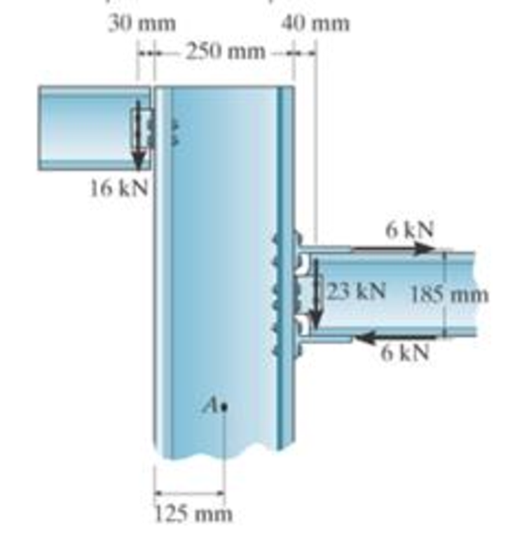
Prob. 7-3
Expert Solution & Answer
Want to see the full answer?
Check out a sample textbook solution
Students have asked these similar questions
Airplanes A and B, flying at constant velocity and at the same altitude, are tracking the eye
of hurricane C. The relative velocity of C with respect to A is 300 kph 65.0° South of West,
and the relative velocity of C with respect to B is 375 kph 50.0° South of East.
A
120.0 km
B
1N
1. Determine the relative velocity of B with respect to A.
A ground-based radar indicates that hurricane C is moving
at a speed of 40.0 kph due north.
2. Determine the velocity of airplane A.
3. Determine the velocity of airplane B.
Consider that at the start of the tracking expedition, the
distance between the planes is 120.0 km and their initial
positions are horizontally collinear.
4. Given the velocities obtained in items 2 and 3, should
the pilots of planes A and B be concerned whether the
planes will collide at any given time? Prove using
pertinent calculations. (Hint: x = x + vt)
0
Only 100% sure experts solve it correct complete solutions okk don't use guidelines or ai answers okk will dislike okkk.
Solve this probem and show all of the work
Chapter 7 Solutions
Engineering Mechanics: Statics Plus Mastering Engineering with Pearson eText -- Access Card Package (14th Edition) (Hibbeler, The Engineering Mechanics: Statics & Dynamics Series, 14th Edition)
Ch. 7.1 - In each case, calculate the reaction at A and then...Ch. 7.1 - Determine the normal force, shear force, and...Ch. 7.1 - Determine the normal force, shear force, and...Ch. 7.1 - Determine the normal force, shear force, and...Ch. 7.1 - Determine the normal force, shear force, and...Ch. 7.1 - Determine the normal force, shear force, and...Ch. 7.1 - Assume A is pinned and B is a roller. Prob. F7-6Ch. 7.1 - Determine the shear force and moment at points C...Ch. 7.1 - Assume the support at B is a roller. Point C is...Ch. 7.1 - Determine the internal normal force, shear force,...
Ch. 7.1 - Determine the internal normal force, shear force,...Ch. 7.1 - If a force of 20 lb is applied to the handles,...Ch. 7.1 - Determine the distance a as a fraction of the...Ch. 7.1 - Determine the internal shear force and moment...Ch. 7.1 - Determine the internal shear force and moment...Ch. 7.1 - Take P = 8 kN. Prob. 7-9Ch. 7.1 - Determine the largest vertical load P the frame...Ch. 7.1 - Determine the internal normal force, shear force,...Ch. 7.1 - Determine the distance a between the bearings in...Ch. 7.1 - Point D is located just to the left of the 5-kip...Ch. 7.1 - The shaft is supported by a journal bearing at A...Ch. 7.1 - Determine the internal normal force, shear force,...Ch. 7.1 - Determine the internal normal force, shear force,...Ch. 7.1 - Determine the normal force, shear force, and...Ch. 7.1 - Determine the internal normal force, shear force,...Ch. 7.1 - Prob. 19PCh. 7.1 - Determine the internal normal force, shear force,...Ch. 7.1 - Point E is located just to the left of 800 N...Ch. 7.1 - Point D is located just to the left of the roller...Ch. 7.1 - Determine the internal normal force, shear force,...Ch. 7.1 - Determine the ratio of a/b for which the shear...Ch. 7.1 - Point E is just to the right of the 3-kip load....Ch. 7.1 - Determine the internal normal force, shear force,...Ch. 7.1 - Determine the internal normal force, shear force,...Ch. 7.1 - Point D is located just to the left of the 10-kN...Ch. 7.1 - Determine the normal force, shear force, and...Ch. 7.1 - Determine the normal force, shear force, and...Ch. 7.1 - Determine the internal normal force, shear force,...Ch. 7.1 - Determine the internal normal force, shear force,...Ch. 7.1 - Determine the internal normal force, shear force,...Ch. 7.1 - Determine the internal normal force, shear force,...Ch. 7.1 - If the suspended load has a weight of 2 kN and a...Ch. 7.1 - Determine the internal normal force, shear force,...Ch. 7.1 - Determine the internal normal force, shear force,...Ch. 7.1 - Determine the internal normal force, shear force,...Ch. 7.1 - The distributed loading W = W0 sin , measured per...Ch. 7.1 - Solve Prob. 7-39 for = 120. Probs. 739/40Ch. 7.1 - z components of force and moment at point C in the...Ch. 7.1 - Determine the x, y, z components of force and...Ch. 7.1 - Determine the x, y, z components of internal...Ch. 7.1 - Determine the x, y. z components of internal...Ch. 7.2 - Determine the shear and moment as a function of x,...Ch. 7.2 - Determine the shear and moment as a function of x,...Ch. 7.2 - Determine the shear and moment as a function of x,...Ch. 7.2 - Determine the shear and moment as a function of x,...Ch. 7.2 - Determine the shear and moment as a function of x,...Ch. 7.2 - Determine the shear and moment as a function of x,...Ch. 7.2 - Draw the shear and moment diagrams for the shaft...Ch. 7.2 - Draw the shear and moment diagrams for the beam...Ch. 7.2 - Draw the shear and moment diagrams for the beam...Ch. 7.2 - Draw the shear and moment diagrams for the...Ch. 7.2 - Draw the shear and moment diagrams of the beam (a)...Ch. 7.2 - If L = 9 m, the beam will fail when the maximum...Ch. 7.2 - Draw the shear and moment diagrams for the beam....Ch. 7.2 - Draw the shear and moment diagrams for the beam....Ch. 7.2 - Draw the shear and bending-moment diagrams for the...Ch. 7.2 - The shaft is supported by a smooth thrust bearing...Ch. 7.2 - Draw the shear and moment diagrams for the beam....Ch. 7.2 - Draw the shear and moment diagrams for the beam....Ch. 7.2 - Draw the shear and moment diagrams for the...Ch. 7.2 - Draw the shear and bending-moment diagrams for...Ch. 7.2 - Draw the shear and moment diagrams for the beam....Ch. 7.2 - The shaft is supported by a smooth thrust bearing...Ch. 7.2 - Draw the shear and moment diagrams for the beam....Ch. 7.2 - The beam will fail when the maximum internal...Ch. 7.2 - Draw the shear and moment diagrams for the beam....Ch. 7.2 - Draw the shear and moment diagrams for the beam....Ch. 7.2 - Draw the shear and moment diagrams for the beam....Ch. 7.2 - Draw the shear and moment diagrams for the beam....Ch. 7.2 - Determine the internal normal force, shear force,...Ch. 7.2 - The quarter circular rod lies in the horizontal...Ch. 7.2 - Express the internal shear and moment components...Ch. 7.3 - Draw the shear and moment diagrams for the beam....Ch. 7.3 - Draw the shear and moment diagrams for the beam....Ch. 7.3 - Draw the shear and moment diagrams for the beam....Ch. 7.3 - Draw the shear and moment diagrams for the beam....Ch. 7.3 - Draw the shear and moment diagrams for the beam....Ch. 7.3 - Draw the shear and moment diagrams for the beam....Ch. 7.3 - Draw the shear and moment diagrams for the beam....Ch. 7.3 - Draw the shear and moment diagrams for the beam....Ch. 7.3 - Draw the shear and moment diagrams for the beam....Ch. 7.3 - Draw the shear and moment diagrams for the...Ch. 7.3 - Draw the shear and moment diagrams for the beam....Ch. 7.3 - Draw the shear and moment diagrams for the beam....Ch. 7.3 - Draw the shear and moment diagrams for the beam....Ch. 7.3 - Draw the shear and moment diagrams for the beam....Ch. 7.3 - Draw the shear and moment diagrams for the beam....Ch. 7.3 - Draw the shear and moment diagrams for the shaft....Ch. 7.3 - Draw the shear and moment diagrams for the beam....Ch. 7.3 - The beam consists of three segments pin connected...Ch. 7.3 - Draw the shear and moment diagrams for the beam....Ch. 7.3 - Draw the shear and moment diagrams for the beam....Ch. 7.3 - Draw the shear and moment diagrams for the beam....Ch. 7.3 - Draw the shear and moment diagrams for the beam....Ch. 7.3 - Draw the shear and moment diagrams for the beam....Ch. 7.3 - Draw the shear and moment diagrams for the beam....Ch. 7.3 - Draw the shear and moment diagrams for the beam....Ch. 7.3 - Draw the shear and moment diagrams for the beam....Ch. 7.3 - Draw the shear and moment diagrams for the beam....Ch. 7.3 - Draw the shear and moment diagrams for the beam....Ch. 7.3 - Draw the shear and moment diagrams for the beam....Ch. 7.3 - Draw the shear and moment diagrams for the beam....Ch. 7.4 - The cable supports the three loads shown....Ch. 7.4 - The cable supports the three loads shown....Ch. 7.4 - Determine the tension in each segment of the cable...Ch. 7.4 - The cable supports the loading shown. Determine...Ch. 7.4 - The cable supports the loading shown. Determine...Ch. 7.4 - The cable supports the three loads shown....Ch. 7.4 - The cable supports the three loads shown....Ch. 7.4 - Determine the force P needed to hold the cable in...Ch. 7.4 - Determine the maximum uniform loading w, measured...Ch. 7.4 - The cable is subjected to a uniform loading of w =...Ch. 7.4 - The cable AB is subjected to a uniform loading of...Ch. 7.4 - Prob. 105PCh. 7.4 - If yB = 1.5 ft. determine the largest weight of...Ch. 7.4 - The cable supports a girder which weighs 850...Ch. 7.4 - Prob. 108PCh. 7.4 - If the pipe has a mass per unit length of 1500...Ch. 7.4 - Prob. 110PCh. 7.4 - Determine the maximum tension developed in the...Ch. 7.4 - Prob. 112PCh. 7.4 - The cable is subjected to the parabolic loading w...Ch. 7.4 - The power transmission cable weighs 10 lb/fl. If...Ch. 7.4 - The power transmission cable weighs 10 lb/ft. If h...Ch. 7.4 - The man picks up the 52-ft chain and holds it just...Ch. 7.4 - Prob. 117PCh. 7.4 - Prob. 118PCh. 7.4 - Prob. 119PCh. 7.4 - A telephone line (cable) stretches between two...Ch. 7.4 - Prob. 121PCh. 7.4 - Prob. 122PCh. 7.4 - A cable has a weight of 5 lb/ft. If it can span...Ch. 7.4 - Prob. 124PCh. 7.4 - Determine the internal normal force, shear force,...Ch. 7.4 - Determine the normal force, shear force, and...Ch. 7.4 - Draw the shear and moment diagrams for the beam....Ch. 7.4 - Draw the shear and moment diagrams for the beam....Ch. 7.4 - Draw the shear and moment diagrams for the beam....Ch. 7.4 - Prob. 6RP
Knowledge Booster


Learn more about
Need a deep-dive on the concept behind this application? Look no further. Learn more about this topic, mechanical-engineering and related others by exploring similar questions and additional content below.Similar questions
- The differential equation of a cruise control system is provided by the following equation: WRITE OUT SOLUTION DO NOT USE A COPIED SOLUTION Find the closed loop transfer function with respect to the reference velocity (vr) . a. Find the poles of the closed loop transfer function for different values of K. How does the poles move as you change K? b. Find the step response for different values of K and plot in MATLAB. What can you observe?arrow_forwardSolve this problem and show all of the workarrow_forwardDetermine the minimum applied force P required to move wedge A to the right. The spring is compressed a distance of 175 mm. Neglect the weight of A and B. The coefficient of static friction for all contacting surface is μs = 0.35. Neglect friction at the rollers. k = = 15 kN/m P A B 10°arrow_forward
- DO NOT COPY SOLUTION- will report The differential equation of a cruise control system is provided by the following equation: Find the closed loop transfer function with respect to the reference velocity (vr) . a. Find the poles of the closed loop transfer function for different values of K. How does the poles move as you change K? b. Find the step response for different values of K and plot in MATLAB. What can you observe?arrow_forwarda box shaped barge 37m long, 6.4 m beam, floats at an even keel draught of 2.5 m in water density 1.025 kg/m3. If a mass is added and the vessel moves into water density 1000 kg/m3, determine the magnitude of this mass if the fore end and aft end draughts are 2.4m and 3.8m respectively.arrow_forwarda ship 125m long and 17.5m beam floats in seawater of 1.025 t/m3 at a draught of 8m. the waterplane coefficient is 0.83, block coefficient 0.759 and midship section area coefficient 0.98. calculate i) prismatic coefficient ii) TPC iii) change in mean draught if the vessel moves into water of 1.016 t/m3arrow_forward
- c. For the given transfer function, find tp, ts, tr, Mp . Plot the resulting step response. G(s) = 40/(s^2 + 4s + 40) handplot only, and solve for eacharrow_forwardA ship of 9000 tonne displacement floats in fresh water of 1.000 t/m3 at a draught 50 mm below the sea water line. The waterplane area is 1650 m2. Calculate the mass of cargo which must be added so that when entering seawater of 1.025 t/m3 it floats at the seawater line.arrow_forwardA ship of 15000 tonne displacement floats at a draught of 7 metres in water of 1.000t/cub. Metre.It is required to load the maximum amount of oil to give the ship a draught of 7.0 metre in seawater ofdensity 1.025 t/cub.metre. If the waterplane area is 2150 square metre, calculate the massof oil requiredarrow_forward
- A ship of 8000 tonne displacement floats in seawater of 1.025 t/m3 and has a TPC of 14. The vessel moves into fresh water of 1.000 t/m3 and loads 300 tonne of oil fuel. Calculate the change in mean draught.arrow_forwardAuto Controls DONT COPY ANSWERS - will report Perform the partial fraction expansion of the following transfer function and find the impulse response: G(s) = (s/2 + 5/3) / (s^2 + 4s + 6) G(s) =( 6s^2 + 50) / (s+3)(s^2 +4)arrow_forwardI submitted the below question and received the answer i copied into this question as well. Im unsure if it is correct, so looking for a checkover. i am stuck on the part tan-1 (0.05) = 0.04996 radians. Just unsure where the value for the radians came from. Just need to know how they got that answer and how it is correct before moving on to the next part. If any of the below information is wrong, please feel free to give me a new answer or an entire new explanation. An Inclining experiment done on a ship thats 6500 t, a mass of 30t was moved 6.0 m transvesly causing a 30 cm deflection in a 6m pendulum, calculate the transverse meta centre height. Here is the step-by-step explanation: Given: Displacement of the ship (W) = 6500 tonnes = 6500×1000=6,500,000kg Mass moved transversely (w) = 30 tonnes=30×1000=30,000kg The transverse shift of mass (d) = 6.0 meters Pendulum length (L) = 6.0 meters Pendulum deflection (x) = 30 cm = 0.30 meters Step 1: Formula for Metacentric Height…arrow_forward
arrow_back_ios
SEE MORE QUESTIONS
arrow_forward_ios
Recommended textbooks for you
 Elements Of ElectromagneticsMechanical EngineeringISBN:9780190698614Author:Sadiku, Matthew N. O.Publisher:Oxford University Press
 Mechanics of Materials (10th Edition)Mechanical EngineeringISBN:9780134319650Author:Russell C. HibbelerPublisher:PEARSON
 Thermodynamics: An Engineering ApproachMechanical EngineeringISBN:9781259822674Author:Yunus A. Cengel Dr., Michael A. BolesPublisher:McGraw-Hill Education
 Control Systems EngineeringMechanical EngineeringISBN:9781118170519Author:Norman S. NisePublisher:WILEY
 Mechanics of Materials (MindTap Course List)Mechanical EngineeringISBN:9781337093347Author:Barry J. Goodno, James M. GerePublisher:Cengage Learning
 Engineering Mechanics: StaticsMechanical EngineeringISBN:9781118807330Author:James L. Meriam, L. G. Kraige, J. N. BoltonPublisher:WILEY
Elements Of Electromagnetics
Mechanical Engineering
ISBN:9780190698614
Author:Sadiku, Matthew N. O.
Publisher:Oxford University Press
Mechanics of Materials (10th Edition)
Mechanical Engineering
ISBN:9780134319650
Author:Russell C. Hibbeler
Publisher:PEARSON
Thermodynamics: An Engineering Approach
Mechanical Engineering
ISBN:9781259822674
Author:Yunus A. Cengel Dr., Michael A. Boles
Publisher:McGraw-Hill Education
Control Systems Engineering
Mechanical Engineering
ISBN:9781118170519
Author:Norman S. Nise
Publisher:WILEY
Mechanics of Materials (MindTap Course List)
Mechanical Engineering
ISBN:9781337093347
Author:Barry J. Goodno, James M. Gere
Publisher:Cengage Learning
Engineering Mechanics: Statics
Mechanical Engineering
ISBN:9781118807330
Author:James L. Meriam, L. G. Kraige, J. N. Bolton
Publisher:WILEY
An Introduction to Stress and Strain; Author: The Efficient Engineer;https://www.youtube.com/watch?v=aQf6Q8t1FQE;License: Standard YouTube License, CC-BY