
Engineering Mechanics: Statics Plus Mastering Engineering with Pearson eText -- Access Card Package (14th Edition) (Hibbeler, The Engineering Mechanics: Statics & Dynamics Series, 14th Edition)
14th Edition
ISBN: 9780134160689
Author: Russell C. Hibbeler
Publisher: PEARSON
expand_more
expand_more
format_list_bulleted
Videos
Textbook Question
Chapter 7.2, Problem 46P
Draw the shear and moment diagrams for the beam (a) in terms of the parameters shown; (b) set P = 8001b, a = 5ft, L = 12 ft.
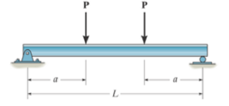
Prob. 7–46
Expert Solution & Answer
Want to see the full answer?
Check out a sample textbook solution
Students have asked these similar questions
Instructions.
"I have written solutions in text form, but I need experts to rewrite them in handwriting from A to Z, exactly as I have written, without any changes."
Pearson eText
Study Area
mylabmastering.pearson.com
Access Pearson
P Pearson MyLab and Mastering
Problem 14.78
P Course Home
b Answered: HW_02.pdf EE 213-01 > Assignments HW_#...
2 of 8
Document Sharing
User Settings
The spring has a stiffness k = 200 N/m and an
unstretched length of 0.5 m. It is attached to the 4.6-kg
smooth collar and the collar is released from rest at A.
Neglect the size of the collar. (Figure 1)
Part A
Determine the speed of the collar when it reaches B.
Express your answer to three significant figures and include the appropriate units.
Figure
1 of 1
με
VB = Value
Units
Submit
Request Answer
Provide Feedback
?
Review
Next >
Pearson eText
Study Area
Access Pearson
mylabmastering.pearson.com
P Pearson MyLab and Mastering
Problem 15.79
P Course Home
b Answered: HW_02.pdf EE 213-01 > Assignments HW_#...
6 of 8
>
Document Sharing
User Settings
The two disks A and B have a mass of 4 kg and 5 kg,
respectively. They collide with the initial velocities shown.
The coefficient of restitution is e = 0.65. Suppose that
(VA)1 = 6 m/s, (VB)1 = 8 m/s. (Figure 1)
Part A
Determine the magnitude of the velocity of A just after impact.
Express your answer to three significant figures and include the appropriate units.
Figure
1 of 1
μÅ
(VA)2 =
Value
Units
Submit
Request Answer
Part B
?
Review
Determine the angle between the x axis and the velocity of A just after impact, measured clockwise from the negative x axis.
Express your answer in degrees to three significant figures.
ΕΠΙ ΑΣΦ
vec
01
Submit
Request Answer
Part C
?
Determine the magnitude of the velocity of B just after impact.
Express your answer to three significant…
Chapter 7 Solutions
Engineering Mechanics: Statics Plus Mastering Engineering with Pearson eText -- Access Card Package (14th Edition) (Hibbeler, The Engineering Mechanics: Statics & Dynamics Series, 14th Edition)
Ch. 7.1 - In each case, calculate the reaction at A and then...Ch. 7.1 - Determine the normal force, shear force, and...Ch. 7.1 - Determine the normal force, shear force, and...Ch. 7.1 - Determine the normal force, shear force, and...Ch. 7.1 - Determine the normal force, shear force, and...Ch. 7.1 - Determine the normal force, shear force, and...Ch. 7.1 - Assume A is pinned and B is a roller. Prob. F7-6Ch. 7.1 - Determine the shear force and moment at points C...Ch. 7.1 - Assume the support at B is a roller. Point C is...Ch. 7.1 - Determine the internal normal force, shear force,...
Ch. 7.1 - Determine the internal normal force, shear force,...Ch. 7.1 - If a force of 20 lb is applied to the handles,...Ch. 7.1 - Determine the distance a as a fraction of the...Ch. 7.1 - Determine the internal shear force and moment...Ch. 7.1 - Determine the internal shear force and moment...Ch. 7.1 - Take P = 8 kN. Prob. 7-9Ch. 7.1 - Determine the largest vertical load P the frame...Ch. 7.1 - Determine the internal normal force, shear force,...Ch. 7.1 - Determine the distance a between the bearings in...Ch. 7.1 - Point D is located just to the left of the 5-kip...Ch. 7.1 - The shaft is supported by a journal bearing at A...Ch. 7.1 - Determine the internal normal force, shear force,...Ch. 7.1 - Determine the internal normal force, shear force,...Ch. 7.1 - Determine the normal force, shear force, and...Ch. 7.1 - Determine the internal normal force, shear force,...Ch. 7.1 - Prob. 19PCh. 7.1 - Determine the internal normal force, shear force,...Ch. 7.1 - Point E is located just to the left of 800 N...Ch. 7.1 - Point D is located just to the left of the roller...Ch. 7.1 - Determine the internal normal force, shear force,...Ch. 7.1 - Determine the ratio of a/b for which the shear...Ch. 7.1 - Point E is just to the right of the 3-kip load....Ch. 7.1 - Determine the internal normal force, shear force,...Ch. 7.1 - Determine the internal normal force, shear force,...Ch. 7.1 - Point D is located just to the left of the 10-kN...Ch. 7.1 - Determine the normal force, shear force, and...Ch. 7.1 - Determine the normal force, shear force, and...Ch. 7.1 - Determine the internal normal force, shear force,...Ch. 7.1 - Determine the internal normal force, shear force,...Ch. 7.1 - Determine the internal normal force, shear force,...Ch. 7.1 - Determine the internal normal force, shear force,...Ch. 7.1 - If the suspended load has a weight of 2 kN and a...Ch. 7.1 - Determine the internal normal force, shear force,...Ch. 7.1 - Determine the internal normal force, shear force,...Ch. 7.1 - Determine the internal normal force, shear force,...Ch. 7.1 - The distributed loading W = W0 sin , measured per...Ch. 7.1 - Solve Prob. 7-39 for = 120. Probs. 739/40Ch. 7.1 - z components of force and moment at point C in the...Ch. 7.1 - Determine the x, y, z components of force and...Ch. 7.1 - Determine the x, y, z components of internal...Ch. 7.1 - Determine the x, y. z components of internal...Ch. 7.2 - Determine the shear and moment as a function of x,...Ch. 7.2 - Determine the shear and moment as a function of x,...Ch. 7.2 - Determine the shear and moment as a function of x,...Ch. 7.2 - Determine the shear and moment as a function of x,...Ch. 7.2 - Determine the shear and moment as a function of x,...Ch. 7.2 - Determine the shear and moment as a function of x,...Ch. 7.2 - Draw the shear and moment diagrams for the shaft...Ch. 7.2 - Draw the shear and moment diagrams for the beam...Ch. 7.2 - Draw the shear and moment diagrams for the beam...Ch. 7.2 - Draw the shear and moment diagrams for the...Ch. 7.2 - Draw the shear and moment diagrams of the beam (a)...Ch. 7.2 - If L = 9 m, the beam will fail when the maximum...Ch. 7.2 - Draw the shear and moment diagrams for the beam....Ch. 7.2 - Draw the shear and moment diagrams for the beam....Ch. 7.2 - Draw the shear and bending-moment diagrams for the...Ch. 7.2 - The shaft is supported by a smooth thrust bearing...Ch. 7.2 - Draw the shear and moment diagrams for the beam....Ch. 7.2 - Draw the shear and moment diagrams for the beam....Ch. 7.2 - Draw the shear and moment diagrams for the...Ch. 7.2 - Draw the shear and bending-moment diagrams for...Ch. 7.2 - Draw the shear and moment diagrams for the beam....Ch. 7.2 - The shaft is supported by a smooth thrust bearing...Ch. 7.2 - Draw the shear and moment diagrams for the beam....Ch. 7.2 - The beam will fail when the maximum internal...Ch. 7.2 - Draw the shear and moment diagrams for the beam....Ch. 7.2 - Draw the shear and moment diagrams for the beam....Ch. 7.2 - Draw the shear and moment diagrams for the beam....Ch. 7.2 - Draw the shear and moment diagrams for the beam....Ch. 7.2 - Determine the internal normal force, shear force,...Ch. 7.2 - The quarter circular rod lies in the horizontal...Ch. 7.2 - Express the internal shear and moment components...Ch. 7.3 - Draw the shear and moment diagrams for the beam....Ch. 7.3 - Draw the shear and moment diagrams for the beam....Ch. 7.3 - Draw the shear and moment diagrams for the beam....Ch. 7.3 - Draw the shear and moment diagrams for the beam....Ch. 7.3 - Draw the shear and moment diagrams for the beam....Ch. 7.3 - Draw the shear and moment diagrams for the beam....Ch. 7.3 - Draw the shear and moment diagrams for the beam....Ch. 7.3 - Draw the shear and moment diagrams for the beam....Ch. 7.3 - Draw the shear and moment diagrams for the beam....Ch. 7.3 - Draw the shear and moment diagrams for the...Ch. 7.3 - Draw the shear and moment diagrams for the beam....Ch. 7.3 - Draw the shear and moment diagrams for the beam....Ch. 7.3 - Draw the shear and moment diagrams for the beam....Ch. 7.3 - Draw the shear and moment diagrams for the beam....Ch. 7.3 - Draw the shear and moment diagrams for the beam....Ch. 7.3 - Draw the shear and moment diagrams for the shaft....Ch. 7.3 - Draw the shear and moment diagrams for the beam....Ch. 7.3 - The beam consists of three segments pin connected...Ch. 7.3 - Draw the shear and moment diagrams for the beam....Ch. 7.3 - Draw the shear and moment diagrams for the beam....Ch. 7.3 - Draw the shear and moment diagrams for the beam....Ch. 7.3 - Draw the shear and moment diagrams for the beam....Ch. 7.3 - Draw the shear and moment diagrams for the beam....Ch. 7.3 - Draw the shear and moment diagrams for the beam....Ch. 7.3 - Draw the shear and moment diagrams for the beam....Ch. 7.3 - Draw the shear and moment diagrams for the beam....Ch. 7.3 - Draw the shear and moment diagrams for the beam....Ch. 7.3 - Draw the shear and moment diagrams for the beam....Ch. 7.3 - Draw the shear and moment diagrams for the beam....Ch. 7.3 - Draw the shear and moment diagrams for the beam....Ch. 7.4 - The cable supports the three loads shown....Ch. 7.4 - The cable supports the three loads shown....Ch. 7.4 - Determine the tension in each segment of the cable...Ch. 7.4 - The cable supports the loading shown. Determine...Ch. 7.4 - The cable supports the loading shown. Determine...Ch. 7.4 - The cable supports the three loads shown....Ch. 7.4 - The cable supports the three loads shown....Ch. 7.4 - Determine the force P needed to hold the cable in...Ch. 7.4 - Determine the maximum uniform loading w, measured...Ch. 7.4 - The cable is subjected to a uniform loading of w =...Ch. 7.4 - The cable AB is subjected to a uniform loading of...Ch. 7.4 - Prob. 105PCh. 7.4 - If yB = 1.5 ft. determine the largest weight of...Ch. 7.4 - The cable supports a girder which weighs 850...Ch. 7.4 - Prob. 108PCh. 7.4 - If the pipe has a mass per unit length of 1500...Ch. 7.4 - Prob. 110PCh. 7.4 - Determine the maximum tension developed in the...Ch. 7.4 - Prob. 112PCh. 7.4 - The cable is subjected to the parabolic loading w...Ch. 7.4 - The power transmission cable weighs 10 lb/fl. If...Ch. 7.4 - The power transmission cable weighs 10 lb/ft. If h...Ch. 7.4 - The man picks up the 52-ft chain and holds it just...Ch. 7.4 - Prob. 117PCh. 7.4 - Prob. 118PCh. 7.4 - Prob. 119PCh. 7.4 - A telephone line (cable) stretches between two...Ch. 7.4 - Prob. 121PCh. 7.4 - Prob. 122PCh. 7.4 - A cable has a weight of 5 lb/ft. If it can span...Ch. 7.4 - Prob. 124PCh. 7.4 - Determine the internal normal force, shear force,...Ch. 7.4 - Determine the normal force, shear force, and...Ch. 7.4 - Draw the shear and moment diagrams for the beam....Ch. 7.4 - Draw the shear and moment diagrams for the beam....Ch. 7.4 - Draw the shear and moment diagrams for the beam....Ch. 7.4 - Prob. 6RP
Knowledge Booster


Learn more about
Need a deep-dive on the concept behind this application? Look no further. Learn more about this topic, mechanical-engineering and related others by exploring similar questions and additional content below.Similar questions
- Pearson eText Study Area mylabmastering.pearson.com Access Pearson P Pearson MyLab and Mastering Problem 14.78 P Course Home b Answered: HW_02.pdf EE 213-01 > Assignments HW_#... 2 of 8 Document Sharing User Settings The spring has a stiffness k = 200 N/m and an unstretched length of 0.5 m. It is attached to the 4.6-kg smooth collar and the collar is released from rest at A. Neglect the size of the collar. (Figure 1) Part A Determine the speed of the collar when it reaches B. Express your answer to three significant figures and include the appropriate units. Figure 1 of 1 με VB = Value Units Submit Request Answer Provide Feedback ? Review Next >arrow_forwardPearson eText Study Area Document Sharing User Settings mylabmastering.pearson.com Access Pearson P Pearson MyLab and Mastering Problem 15.96 Part A In (Figure 1), take m₁ = 3.4 kg and m = 4.8 kg. Figure 1 of 1 P Course Home b Answered: HW_02.pdf EE 213-01 > Assignments HW_#... 7 of 8 Determine the component of the angular momentum Ho of particle A about point O. Express your answer in kilogram-meters squared per second to three significant figures. (Ho) z = -ΜΕ ΑΣΦ vec Submit Request Answer Part B ? kg m2/s Determine the component of the angular momentum Ho of particle B about point O. Suppose that Express your answer in kilogram-meters squared per second to three significant figures. ΜΕ ΑΣΦ vec Symbols (Ho)z = Submit Request Answer Provide Feedback ? kg m2/s Review Next >arrow_forwardPearson eText Study Area Document Sharing User Settings mylabmastering.pearson.com Access Pearson P Pearson MyLab and Mastering Problem 14.69 Part A P Course Home b Answered: HW_02.pdf EE 213-01 > Assignments HW_#... 1 of 8 Review The 5-kg collar has a velocity of 7 m/s to the right when it is at A. It then travels down along the smooth guide shown in (Figure 1). The spring has an unstretched length of 100 mm and B is located just before the end of the curved portion of the rod. Determine the speed of the collar when it reaches point B, which is located just before the end of the curved portion of the rod. Express your answer to three significant figures and include the appropriate units. Figure 1 of 1 με v = Value Units Submit Request Answer Part B ? What is the normal force on the collar at this instant? Express your answer to three significant figures and include the appropriate units. ☐ μÅ ? N = Value Units Submit Request Answer Provide Feedback Next >arrow_forward
- Pearson eText Study Area mylabmastering.pearson.com Access Pearson P Pearson MyLab and Mastering Problem 15.106 P Course Home b Answered: HW_02.pdf EE 213-01 > Assignments HW_#... 8 of 8 Document Sharing User Settings The two spheres A and B each have a mass of 400 g. The spheres are fixed to the horizontal rods as shown in (Figure 1) and their initial velocity is 2 m/s. The mass of the supporting frame is negligible and it is free to rotate. Neglect the size of the spheres. Part A If a couple moment of M = 0.3 N · m is applied to the frame, determine the speed of the spheres in 3 s. Express your answer to three significant figures and include the appropriate units. Figure 1 of 1 ☐ ? v = Value Units Units input for part A Submit Request Answer Return to Assignment Provide Feedback ■Reviewarrow_forwardPearson eText Study Area Access Pearson mylabmastering.pearson.com P Pearson MyLab and Mastering Problem 15.79 P Course Home b Answered: HW_02.pdf EE 213-01 > Assignments HW_#... 6 of 8 > Document Sharing User Settings The two disks A and B have a mass of 4 kg and 5 kg, respectively. They collide with the initial velocities shown. The coefficient of restitution is e = 0.65. Suppose that (VA)1 = 6 m/s, (VB)1 = 8 m/s. (Figure 1) Part A Determine the magnitude of the velocity of A just after impact. Express your answer to three significant figures and include the appropriate units. Figure 1 of 1 μÅ (VA)2 = Value Units Submit Request Answer Part B ? Review Determine the angle between the x axis and the velocity of A just after impact, measured clockwise from the negative x axis. Express your answer in degrees to three significant figures. ΕΠΙ ΑΣΦ vec 01 Submit Request Answer Part C ? Determine the magnitude of the velocity of B just after impact. Express your answer to three significant…arrow_forward40.00 30.00 100.00- 100.00 P = 1000 N A=167 d=140.00 100.00- -b 20.00 200.00 Weld Strength P = 273 N/mm^2 Electrod E60 Safety factor S₁ = 3 Force P = 1000 N Using by SOLIDWORKSarrow_forward
- What are the reaction forces in A and B?arrow_forwardPearson eText Study Area Access Pearson mylabmastering.pearson.com P Pearson MyLab and Mastering Problem 15.6 P Course Home b Answered: HW_02.pdf EE 213-01 > Assignments HW_#... 3 of 8 ■ Review Document Sharing User Settings The jet plane has a mass of 250 Mg and a horizontal velocity of 100 m/s when t = 0. Part A If both engines provide a horizontal thrust which varies as shown in the graph in (Figure 1), determine the plane's velocity in 5 s. Neglect air resistance and the loss of fuel during the motion. Express your answer to three significant figures and include the appropriate units. Figure 1 of 1 > ☐ μÅ ? v = Value Units Submit Request Answer Provide Feedback Next >arrow_forwardAccess Pearson mylabmastering.pearson.com P Pearson MyLab and Mastering Problem 15.43 P Course Home b Answered: HW_02.pdf EE 213-01 > Assignments HW_#... Pearson eText Study Area Document Sharing User Settings The 20-g bullet is travelling at 400 m/s when it becomes embedded in the 2-kg stationary block. The coefficient of kinetic friction between the block and the plane is μk = 0.2. (Figure 1) Part A Determine the distance the block will slide before it stops. Express your answer to three significant figures and include the appropriate units. Figure 1 of 1 με S = Value Units Submit Request Answer Provide Feedback ? 4 of 8 Review Next >arrow_forward
- Access Pearson mylabmastering.pearson.com P Pearson MyLab and Mastering Problem 15.64 P Course Home b Answered: HW_02.pdf EE 213-01 > Assignments HW_#... 5 of 8 Pearson eText Study Area Document Sharing User Settings Ball A has a mass of 3 kg and is moving with a velocity of (VA)1 = 8 m/s when it makes a direct collision with ball B, which has a mass of 2.5 kg and is moving with a velocity of (VB) 1 = 4 m/s. Suppose that e = 0.7. Neglect the size of the balls. (Figure 1) Part A Determine the velocity of A just after the collision. ■Review Express your answer to three significant figures and include the appropriate units. Assume the positive direction is to the right. Figure 1 of 1 ◎ на ? (VA)2= Value Units Submit Request Answer Part B Determine the velocity of B just after the collision. Express your answer to three significant figures and include the appropriate units. Assume the positive direction is to the right. μÅ ? (VB)2= = Value Units Submit Request Answer Provide Feedback Next…arrow_forwardI only need help with number 3, actually just the theta dot portion. Thanks! I have Vr = 10.39 ft/sarrow_forwardOnly 100% sure experts solve it correct complete solutions okk don't use guidelines or ai answers okk will dislike okkk. Only human experts solved itarrow_forward
arrow_back_ios
SEE MORE QUESTIONS
arrow_forward_ios
Recommended textbooks for you
 Elements Of ElectromagneticsMechanical EngineeringISBN:9780190698614Author:Sadiku, Matthew N. O.Publisher:Oxford University Press
 Mechanics of Materials (10th Edition)Mechanical EngineeringISBN:9780134319650Author:Russell C. HibbelerPublisher:PEARSON
 Thermodynamics: An Engineering ApproachMechanical EngineeringISBN:9781259822674Author:Yunus A. Cengel Dr., Michael A. BolesPublisher:McGraw-Hill Education
 Control Systems EngineeringMechanical EngineeringISBN:9781118170519Author:Norman S. NisePublisher:WILEY
 Mechanics of Materials (MindTap Course List)Mechanical EngineeringISBN:9781337093347Author:Barry J. Goodno, James M. GerePublisher:Cengage Learning
 Engineering Mechanics: StaticsMechanical EngineeringISBN:9781118807330Author:James L. Meriam, L. G. Kraige, J. N. BoltonPublisher:WILEY
Elements Of Electromagnetics
Mechanical Engineering
ISBN:9780190698614
Author:Sadiku, Matthew N. O.
Publisher:Oxford University Press
Mechanics of Materials (10th Edition)
Mechanical Engineering
ISBN:9780134319650
Author:Russell C. Hibbeler
Publisher:PEARSON
Thermodynamics: An Engineering Approach
Mechanical Engineering
ISBN:9781259822674
Author:Yunus A. Cengel Dr., Michael A. Boles
Publisher:McGraw-Hill Education
Control Systems Engineering
Mechanical Engineering
ISBN:9781118170519
Author:Norman S. Nise
Publisher:WILEY
Mechanics of Materials (MindTap Course List)
Mechanical Engineering
ISBN:9781337093347
Author:Barry J. Goodno, James M. Gere
Publisher:Cengage Learning
Engineering Mechanics: Statics
Mechanical Engineering
ISBN:9781118807330
Author:James L. Meriam, L. G. Kraige, J. N. Bolton
Publisher:WILEY
Mechanics of Materials Lecture: Beam Design; Author: UWMC Engineering;https://www.youtube.com/watch?v=-wVs5pvQPm4;License: Standard Youtube License