
ENGINEERING MECHANICS Â?? STATICS
15th Edition
ISBN: 9780137519132
Author: HIBBELER
Publisher: PEARSON
expand_more
expand_more
format_list_bulleted
Concept explainers
Videos
Textbook Question
Chapter 7.1, Problem 25P
Point E is just to the right of the 3-kip load.
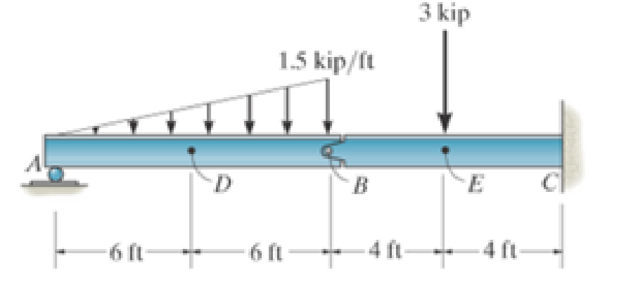
Prob. 7-25
Expert Solution & Answer
Want to see the full answer?
Check out a sample textbook solution
Students have asked these similar questions
Problem 5 (Optional, extra 6 points)
A 6-lb homogeneous disk of radius 3 in. spins as shown at the constant rate w₁ = 60 rad/s. The disk
is supported by the fork-ended rod AB, which is welded to the vertical shaft CBD. The system is
at rest when a couple Mo= (0.25ft-lb)j is applied to the shaft for 2 s and then removed. Determine
the dynamic reactions at C and D before and after the couple has been removed at 2 s.
4 in.
C
B
Mo
5 in
4 in.
Note: 2 rotating around CD induced by Mo is NOT
constant before Mo is removed.
and ₂ (two
unknowns) are related by the equation: ₂ =0+ w₂t
3 in.
Partial Answer (after Mo has been removed):
C-7.81+7.43k lb
D -7.81 7.43 lb
Problem 4.
A homogeneous disk with radius and mass m is mounted on an axle OG with length L and a
negligible mass. The axle is pivoted at the fixed-point O, and the disk is constrained to roll on a
horizontal surface. The disk rotates counterclockwise at the constant rate o₁ about the axle. (mg
must be included into your calculation)
(a). Calculate the linear velocity of G and indicate it on the figure.
(b). Calculate ₂ (constant), which is the angular velocity of the
axle OG around the vertical axis.
(c). Calculate the linear acceleration ā of G and indicate it on the
figure.
(d). Determine the force (assumed vertical) exerted by the floor on
the disk
(e). Determine the reaction at the pivot O.
1
Answers: N = mg +mr(r/L)² @² |j
mr w
IIG
C
R
L
i+
2L
=
Problem 2.
The homogeneous disk of weight W = 6 lb rotates at the constant rate co₁ = 16 rad/s with respect
to arm ABC, which is welded to a shaft DCE rotating at the constant rate 2 = 8 rad/s. Assume
the rod weight is negligible compared to the disk. Determine the dynamic reactions at D and E
(ignore mg).
Answers:
D=-7.12ĵ+4.47k lb
r-8 in.
9 in.
B
D
E=-1.822+4.47 lb
9 in.
E
12 in.
12 in.
x
Chapter 7 Solutions
ENGINEERING MECHANICS Â?? STATICS
Ch. 7.1 - In each case, calculate the reaction at A and then...Ch. 7.1 - Determine the normal force, shear force, and...Ch. 7.1 - Determine the normal force, shear force, and...Ch. 7.1 - Determine the normal force, shear force, and...Ch. 7.1 - Determine the normal force, shear force, and...Ch. 7.1 - Determine the normal force, shear force, and...Ch. 7.1 - Assume A is pinned and B is a roller. Prob. F7-6Ch. 7.1 - Determine the shear force and moment at points C...Ch. 7.1 - Assume the support at B is a roller. Point C is...Ch. 7.1 - Determine the internal normal force, shear force,...
Ch. 7.1 - Determine the internal normal force, shear force,...Ch. 7.1 - If a force of 20 lb is applied to the handles,...Ch. 7.1 - Determine the distance a as a fraction of the...Ch. 7.1 - Determine the internal shear force and moment...Ch. 7.1 - Determine the internal shear force and moment...Ch. 7.1 - Take P = 8 kN. Prob. 7-9Ch. 7.1 - Determine the largest vertical load P the frame...Ch. 7.1 - Determine the internal normal force, shear force,...Ch. 7.1 - Determine the distance a between the bearings in...Ch. 7.1 - Point D is located just to the left of the 5-kip...Ch. 7.1 - The shaft is supported by a journal bearing at A...Ch. 7.1 - Determine the internal normal force, shear force,...Ch. 7.1 - Determine the internal normal force, shear force,...Ch. 7.1 - Determine the normal force, shear force, and...Ch. 7.1 - Determine the internal normal force, shear force,...Ch. 7.1 - Prob. 19PCh. 7.1 - Determine the internal normal force, shear force,...Ch. 7.1 - Point E is located just to the left of 800 N...Ch. 7.1 - Point D is located just to the left of the roller...Ch. 7.1 - Determine the internal normal force, shear force,...Ch. 7.1 - Determine the ratio of a/b for which the shear...Ch. 7.1 - Point E is just to the right of the 3-kip load....Ch. 7.1 - Determine the internal normal force, shear force,...Ch. 7.1 - Determine the internal normal force, shear force,...Ch. 7.1 - Point D is located just to the left of the 10-kN...Ch. 7.1 - Determine the normal force, shear force, and...Ch. 7.1 - Determine the normal force, shear force, and...Ch. 7.1 - Determine the internal normal force, shear force,...Ch. 7.1 - Determine the internal normal force, shear force,...Ch. 7.1 - Determine the internal normal force, shear force,...Ch. 7.1 - Determine the internal normal force, shear force,...Ch. 7.1 - If the suspended load has a weight of 2 kN and a...Ch. 7.1 - Determine the internal normal force, shear force,...Ch. 7.1 - Determine the internal normal force, shear force,...Ch. 7.1 - Determine the internal normal force, shear force,...Ch. 7.1 - The distributed loading W = W0 sin , measured per...Ch. 7.1 - Solve Prob. 7-39 for = 120. Probs. 739/40Ch. 7.1 - z components of force and moment at point C in the...Ch. 7.1 - Determine the x, y, z components of force and...Ch. 7.1 - Determine the x, y, z components of internal...Ch. 7.1 - Determine the x, y. z components of internal...Ch. 7.2 - Determine the shear and moment as a function of x,...Ch. 7.2 - Determine the shear and moment as a function of x,...Ch. 7.2 - Determine the shear and moment as a function of x,...Ch. 7.2 - Determine the shear and moment as a function of x,...Ch. 7.2 - Determine the shear and moment as a function of x,...Ch. 7.2 - Determine the shear and moment as a function of x,...Ch. 7.2 - Draw the shear and moment diagrams for the shaft...Ch. 7.2 - Draw the shear and moment diagrams for the beam...Ch. 7.2 - Draw the shear and moment diagrams for the beam...Ch. 7.2 - Draw the shear and moment diagrams for the...Ch. 7.2 - Draw the shear and moment diagrams of the beam (a)...Ch. 7.2 - If L = 9 m, the beam will fail when the maximum...Ch. 7.2 - Draw the shear and moment diagrams for the beam....Ch. 7.2 - Draw the shear and moment diagrams for the beam....Ch. 7.2 - Draw the shear and bending-moment diagrams for the...Ch. 7.2 - The shaft is supported by a smooth thrust bearing...Ch. 7.2 - Draw the shear and moment diagrams for the beam....Ch. 7.2 - Draw the shear and moment diagrams for the beam....Ch. 7.2 - Draw the shear and moment diagrams for the...Ch. 7.2 - Draw the shear and bending-moment diagrams for...Ch. 7.2 - Draw the shear and moment diagrams for the beam....Ch. 7.2 - The shaft is supported by a smooth thrust bearing...Ch. 7.2 - Draw the shear and moment diagrams for the beam....Ch. 7.2 - The beam will fail when the maximum internal...Ch. 7.2 - Draw the shear and moment diagrams for the beam....Ch. 7.2 - Draw the shear and moment diagrams for the beam....Ch. 7.2 - Draw the shear and moment diagrams for the beam....Ch. 7.2 - Draw the shear and moment diagrams for the beam....Ch. 7.2 - Determine the internal normal force, shear force,...Ch. 7.2 - The quarter circular rod lies in the horizontal...Ch. 7.2 - Express the internal shear and moment components...Ch. 7.3 - Draw the shear and moment diagrams for the beam....Ch. 7.3 - Draw the shear and moment diagrams for the beam....Ch. 7.3 - Draw the shear and moment diagrams for the beam....Ch. 7.3 - Draw the shear and moment diagrams for the beam....Ch. 7.3 - Draw the shear and moment diagrams for the beam....Ch. 7.3 - Draw the shear and moment diagrams for the beam....Ch. 7.3 - Draw the shear and moment diagrams for the beam....Ch. 7.3 - Draw the shear and moment diagrams for the beam....Ch. 7.3 - Draw the shear and moment diagrams for the beam....Ch. 7.3 - Draw the shear and moment diagrams for the...Ch. 7.3 - Draw the shear and moment diagrams for the beam....Ch. 7.3 - Draw the shear and moment diagrams for the beam....Ch. 7.3 - Draw the shear and moment diagrams for the beam....Ch. 7.3 - Draw the shear and moment diagrams for the beam....Ch. 7.3 - Draw the shear and moment diagrams for the beam....Ch. 7.3 - Draw the shear and moment diagrams for the shaft....Ch. 7.3 - Draw the shear and moment diagrams for the beam....Ch. 7.3 - The beam consists of three segments pin connected...Ch. 7.3 - Draw the shear and moment diagrams for the beam....Ch. 7.3 - Draw the shear and moment diagrams for the beam....Ch. 7.3 - Draw the shear and moment diagrams for the beam....Ch. 7.3 - Draw the shear and moment diagrams for the beam....Ch. 7.3 - Draw the shear and moment diagrams for the beam....Ch. 7.3 - Draw the shear and moment diagrams for the beam....Ch. 7.3 - Draw the shear and moment diagrams for the beam....Ch. 7.3 - Draw the shear and moment diagrams for the beam....Ch. 7.3 - Draw the shear and moment diagrams for the beam....Ch. 7.3 - Draw the shear and moment diagrams for the beam....Ch. 7.3 - Draw the shear and moment diagrams for the beam....Ch. 7.3 - Draw the shear and moment diagrams for the beam....Ch. 7.4 - The cable supports the three loads shown....Ch. 7.4 - The cable supports the three loads shown....Ch. 7.4 - Determine the tension in each segment of the cable...Ch. 7.4 - The cable supports the loading shown. Determine...Ch. 7.4 - The cable supports the loading shown. Determine...Ch. 7.4 - The cable supports the three loads shown....Ch. 7.4 - The cable supports the three loads shown....Ch. 7.4 - Determine the force P needed to hold the cable in...Ch. 7.4 - Determine the maximum uniform loading w, measured...Ch. 7.4 - The cable is subjected to a uniform loading of w =...Ch. 7.4 - The cable AB is subjected to a uniform loading of...Ch. 7.4 - Prob. 105PCh. 7.4 - If yB = 1.5 ft. determine the largest weight of...Ch. 7.4 - The cable supports a girder which weighs 850...Ch. 7.4 - Prob. 108PCh. 7.4 - If the pipe has a mass per unit length of 1500...Ch. 7.4 - Prob. 110PCh. 7.4 - Determine the maximum tension developed in the...Ch. 7.4 - Prob. 112PCh. 7.4 - The cable is subjected to the parabolic loading w...Ch. 7.4 - The power transmission cable weighs 10 lb/fl. If...Ch. 7.4 - The power transmission cable weighs 10 lb/ft. If h...Ch. 7.4 - The man picks up the 52-ft chain and holds it just...Ch. 7.4 - Prob. 117PCh. 7.4 - Prob. 118PCh. 7.4 - Prob. 119PCh. 7.4 - A telephone line (cable) stretches between two...Ch. 7.4 - Prob. 121PCh. 7.4 - Prob. 122PCh. 7.4 - A cable has a weight of 5 lb/ft. If it can span...Ch. 7.4 - Prob. 124PCh. 7.4 - Determine the internal normal force, shear force,...Ch. 7.4 - Determine the normal force, shear force, and...Ch. 7.4 - Draw the shear and moment diagrams for the beam....Ch. 7.4 - Draw the shear and moment diagrams for the beam....Ch. 7.4 - Draw the shear and moment diagrams for the beam....Ch. 7.4 - Prob. 6RP
Knowledge Booster


Learn more about
Need a deep-dive on the concept behind this application? Look no further. Learn more about this topic, mechanical-engineering and related others by exploring similar questions and additional content below.Similar questions
- Problem 3. Each of the right angle rods has a mass of 120 g and is welded to the shaft, which rotates at a steady speed of 3600 rpm. Ignore the weight of the shaft AB. Find the bearing dynamic reaction at A due to the dynamic imbalance of the shaft. (ignore mgs) 100 N A 100 100 100 100 100 (Dimensions in millimeters) Answer: A=-8521-426j N Barrow_forwardThermodynamics. Need help solving this. Step by step with unitsarrow_forwardQuiz/An eccentrically loaded bracket is welded to the support as shown in Figure below. The load is static. The weld size for weld w1 is h1 = 4mm, for w2 h2=6mm, and for w3 is h3 -6.5 mm. Determine the safety factor (S.f) for the welds. F=29 kN. Use an AWS Electrode type (E100xx). 163 mm 133 mm 140 mm w3 wiarrow_forward
- E W X FO FB F10 F11 F12 Home Q: Consider the square of Figure below.The left face is maintained at 100°C and the top face at 500°C, while the other two faces are exposed to an environment at1 00°C, h=10 W/m². C and k=10 W/m.°C. The block is 1 m square. Compute the temperature of the various nodes as indicated in Figure below and the heat flows at the boundaries. T= 500°C Alt Explain to me in detail how to calculate the matrix in the Casio calculator type (fx-991ES plus) T= 100°C 1 2 4 7 1 m- 3 1 m 5 6 T= 100°C 8 9arrow_forwardWhich of the following sequences converge and which diverge? 1) a₁ = 2+(0.1)" 1-2n 2) a = 1+2n 1/n 3 16) a = n In n 17) an = n 1/n 1-5n4 3) an = n² +8n³ 18) an = √4" n n² -2n+1 n! 20) a = 4) an = 106 5) n-1 a₁ =1+(-1)" n+1 a-(+) (1-4) 6) = 7) a = 2n (-1)"+1 2n-1 21) an = n -A" 1/(Inn) 3n+1 22) a = 3n-1 1/n x" 23) a = , x>0 2n+1 3" x 6" 24) a = 2™" xn! 2n 8) a = n+1 πT 1 9) a„ = sin +- 2 n sin n 10) an = n 25) a = tanh(n) 26) a = 2n-1 27) a = tan(n) 1 -sin n n 11) a = 2" 28) an == " 1 + 2" In(n+1) 12) a = n (In n) 200 29) a = n 13) a = 8/n 14) a 1+ =(1+²)" 15) an 7 n = 10n 30) an-√√n²-n 1"1 31) adx nixarrow_forwardA steel alloy contains 95.7 wt% Fe, 4.0 wt% W, and 0.3 wt% C.arrow_forward
- b. A horizontal cantilever of effective length 3a, carries two concentrated loads W at a distance a from the fixed end and W' at a distance a from the free end. Obtain a formula for the maximum deflection due to this loading using Mohr's method. If the cantilever is 250 mm by 150mm steel I beam, 3 m long having a second moment of area I as 8500 cm4, determine W and W'to give a maximum deflection of 6 mm when the maximum stress due to bending is 90 Mpa. Take Young's modulus of material E as 185 Gpa.arrow_forwardWhich of the following sequences converge and which diverge? 1/n 1) a₁ = 2+(0.1)" 3 16) a = n 1-2n 2) a = In n 1+2n 17) an = 1/n n 1-5n4 3) an = n² +8n³ 18) an = √4" n n! n² -2n+1 20) a = 4) an = 106 5) n-1 a₁ =1+(-1)" n+1 a-(+) (1-4) 6) = 7) a = 2n (-1)"+1 2n-1 21) an = n -A" 1/(Inn) 3n+1 22) a = 3n-1 1/n x" 23) a = , x>0 2n+1 3" x 6" 24) a = 2™" xn! 2n 8) a = n+1 πT 1 9) a„ = sin +- 2 n sin n 10) an = n 25) a = tanh(n) 26) a = 2n-1 27) a = tan(n) 1 -sin n n 11) a = 2" 28) an == " 1 + 2" In(n+1) 12) a = n (In n) 200 29) a = n 13) a = 8/n 14) a 1+ =(1+²)" 15) an 7 n = 10n 30) an-√√n²-n 1"1 31) adx nixarrow_forwardCalculate the angle of incidence of beam radiation on a collector located at (Latitude 17.40S) on June 15 at 1030hrs solar time. The collector is tilted at an angle of 200, with a surface azimuth angle of 150.arrow_forward
arrow_back_ios
SEE MORE QUESTIONS
arrow_forward_ios
Recommended textbooks for you
 International Edition---engineering Mechanics: St...Mechanical EngineeringISBN:9781305501607Author:Andrew Pytel And Jaan KiusalaasPublisher:CENGAGE L
International Edition---engineering Mechanics: St...
Mechanical Engineering
ISBN:9781305501607
Author:Andrew Pytel And Jaan Kiusalaas
Publisher:CENGAGE L
moment of inertia; Author: NCERT OFFICIAL;https://www.youtube.com/watch?v=A4KhJYrt4-s;License: Standard YouTube License, CC-BY