
ENGINEERING MECHANICS Â?? STATICS
15th Edition
ISBN: 9780137519132
Author: HIBBELER
Publisher: PEARSON
expand_more
expand_more
format_list_bulleted
Concept explainers
Videos
Textbook Question
Chapter 7.1, Problem 1P
Determine the shear force and moment at points C and D.
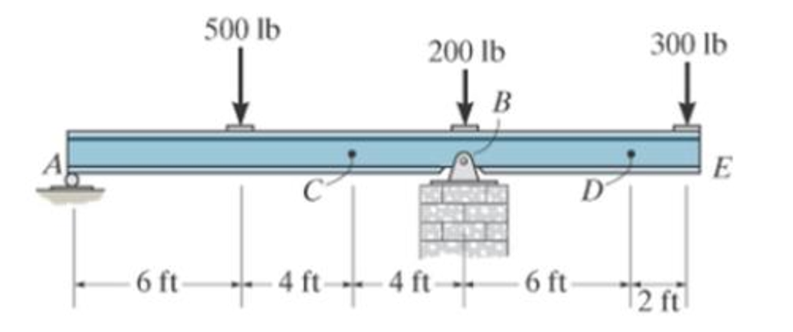
Prob. 7-1
Expert Solution & Answer

Learn your wayIncludes step-by-step video

schedule09:43
Students have asked these similar questions
handwritten-solutions, please!
Required information
An eccentric force P is applied as shown to a steel bar of 25 × 90-mm cross section. The strains at A and B have been
measured and found to be
εΑ = +490 μ
εB=-70 μ
Know that E = 200 GPa.
25 mm
30 mm
90 mm
45 mm
B
Determine the distance d.
The distance dis
15 mm
mm.
handwritten-solutions, please!
Chapter 7 Solutions
ENGINEERING MECHANICS Â?? STATICS
Ch. 7.1 - In each case, calculate the reaction at A and then...Ch. 7.1 - Determine the normal force, shear force, and...Ch. 7.1 - Determine the normal force, shear force, and...Ch. 7.1 - Determine the normal force, shear force, and...Ch. 7.1 - Determine the normal force, shear force, and...Ch. 7.1 - Determine the normal force, shear force, and...Ch. 7.1 - Assume A is pinned and B is a roller. Prob. F7-6Ch. 7.1 - Determine the shear force and moment at points C...Ch. 7.1 - Assume the support at B is a roller. Point C is...Ch. 7.1 - Determine the internal normal force, shear force,...
Ch. 7.1 - Determine the internal normal force, shear force,...Ch. 7.1 - If a force of 20 lb is applied to the handles,...Ch. 7.1 - Determine the distance a as a fraction of the...Ch. 7.1 - Determine the internal shear force and moment...Ch. 7.1 - Determine the internal shear force and moment...Ch. 7.1 - Take P = 8 kN. Prob. 7-9Ch. 7.1 - Determine the largest vertical load P the frame...Ch. 7.1 - Determine the internal normal force, shear force,...Ch. 7.1 - Determine the distance a between the bearings in...Ch. 7.1 - Point D is located just to the left of the 5-kip...Ch. 7.1 - The shaft is supported by a journal bearing at A...Ch. 7.1 - Determine the internal normal force, shear force,...Ch. 7.1 - Determine the internal normal force, shear force,...Ch. 7.1 - Determine the normal force, shear force, and...Ch. 7.1 - Determine the internal normal force, shear force,...Ch. 7.1 - Prob. 19PCh. 7.1 - Determine the internal normal force, shear force,...Ch. 7.1 - Point E is located just to the left of 800 N...Ch. 7.1 - Point D is located just to the left of the roller...Ch. 7.1 - Determine the internal normal force, shear force,...Ch. 7.1 - Determine the ratio of a/b for which the shear...Ch. 7.1 - Point E is just to the right of the 3-kip load....Ch. 7.1 - Determine the internal normal force, shear force,...Ch. 7.1 - Determine the internal normal force, shear force,...Ch. 7.1 - Point D is located just to the left of the 10-kN...Ch. 7.1 - Determine the normal force, shear force, and...Ch. 7.1 - Determine the normal force, shear force, and...Ch. 7.1 - Determine the internal normal force, shear force,...Ch. 7.1 - Determine the internal normal force, shear force,...Ch. 7.1 - Determine the internal normal force, shear force,...Ch. 7.1 - Determine the internal normal force, shear force,...Ch. 7.1 - If the suspended load has a weight of 2 kN and a...Ch. 7.1 - Determine the internal normal force, shear force,...Ch. 7.1 - Determine the internal normal force, shear force,...Ch. 7.1 - Determine the internal normal force, shear force,...Ch. 7.1 - The distributed loading W = W0 sin , measured per...Ch. 7.1 - Solve Prob. 7-39 for = 120. Probs. 739/40Ch. 7.1 - z components of force and moment at point C in the...Ch. 7.1 - Determine the x, y, z components of force and...Ch. 7.1 - Determine the x, y, z components of internal...Ch. 7.1 - Determine the x, y. z components of internal...Ch. 7.2 - Determine the shear and moment as a function of x,...Ch. 7.2 - Determine the shear and moment as a function of x,...Ch. 7.2 - Determine the shear and moment as a function of x,...Ch. 7.2 - Determine the shear and moment as a function of x,...Ch. 7.2 - Determine the shear and moment as a function of x,...Ch. 7.2 - Determine the shear and moment as a function of x,...Ch. 7.2 - Draw the shear and moment diagrams for the shaft...Ch. 7.2 - Draw the shear and moment diagrams for the beam...Ch. 7.2 - Draw the shear and moment diagrams for the beam...Ch. 7.2 - Draw the shear and moment diagrams for the...Ch. 7.2 - Draw the shear and moment diagrams of the beam (a)...Ch. 7.2 - If L = 9 m, the beam will fail when the maximum...Ch. 7.2 - Draw the shear and moment diagrams for the beam....Ch. 7.2 - Draw the shear and moment diagrams for the beam....Ch. 7.2 - Draw the shear and bending-moment diagrams for the...Ch. 7.2 - The shaft is supported by a smooth thrust bearing...Ch. 7.2 - Draw the shear and moment diagrams for the beam....Ch. 7.2 - Draw the shear and moment diagrams for the beam....Ch. 7.2 - Draw the shear and moment diagrams for the...Ch. 7.2 - Draw the shear and bending-moment diagrams for...Ch. 7.2 - Draw the shear and moment diagrams for the beam....Ch. 7.2 - The shaft is supported by a smooth thrust bearing...Ch. 7.2 - Draw the shear and moment diagrams for the beam....Ch. 7.2 - The beam will fail when the maximum internal...Ch. 7.2 - Draw the shear and moment diagrams for the beam....Ch. 7.2 - Draw the shear and moment diagrams for the beam....Ch. 7.2 - Draw the shear and moment diagrams for the beam....Ch. 7.2 - Draw the shear and moment diagrams for the beam....Ch. 7.2 - Determine the internal normal force, shear force,...Ch. 7.2 - The quarter circular rod lies in the horizontal...Ch. 7.2 - Express the internal shear and moment components...Ch. 7.3 - Draw the shear and moment diagrams for the beam....Ch. 7.3 - Draw the shear and moment diagrams for the beam....Ch. 7.3 - Draw the shear and moment diagrams for the beam....Ch. 7.3 - Draw the shear and moment diagrams for the beam....Ch. 7.3 - Draw the shear and moment diagrams for the beam....Ch. 7.3 - Draw the shear and moment diagrams for the beam....Ch. 7.3 - Draw the shear and moment diagrams for the beam....Ch. 7.3 - Draw the shear and moment diagrams for the beam....Ch. 7.3 - Draw the shear and moment diagrams for the beam....Ch. 7.3 - Draw the shear and moment diagrams for the...Ch. 7.3 - Draw the shear and moment diagrams for the beam....Ch. 7.3 - Draw the shear and moment diagrams for the beam....Ch. 7.3 - Draw the shear and moment diagrams for the beam....Ch. 7.3 - Draw the shear and moment diagrams for the beam....Ch. 7.3 - Draw the shear and moment diagrams for the beam....Ch. 7.3 - Draw the shear and moment diagrams for the shaft....Ch. 7.3 - Draw the shear and moment diagrams for the beam....Ch. 7.3 - The beam consists of three segments pin connected...Ch. 7.3 - Draw the shear and moment diagrams for the beam....Ch. 7.3 - Draw the shear and moment diagrams for the beam....Ch. 7.3 - Draw the shear and moment diagrams for the beam....Ch. 7.3 - Draw the shear and moment diagrams for the beam....Ch. 7.3 - Draw the shear and moment diagrams for the beam....Ch. 7.3 - Draw the shear and moment diagrams for the beam....Ch. 7.3 - Draw the shear and moment diagrams for the beam....Ch. 7.3 - Draw the shear and moment diagrams for the beam....Ch. 7.3 - Draw the shear and moment diagrams for the beam....Ch. 7.3 - Draw the shear and moment diagrams for the beam....Ch. 7.3 - Draw the shear and moment diagrams for the beam....Ch. 7.3 - Draw the shear and moment diagrams for the beam....Ch. 7.4 - The cable supports the three loads shown....Ch. 7.4 - The cable supports the three loads shown....Ch. 7.4 - Determine the tension in each segment of the cable...Ch. 7.4 - The cable supports the loading shown. Determine...Ch. 7.4 - The cable supports the loading shown. Determine...Ch. 7.4 - The cable supports the three loads shown....Ch. 7.4 - The cable supports the three loads shown....Ch. 7.4 - Determine the force P needed to hold the cable in...Ch. 7.4 - Determine the maximum uniform loading w, measured...Ch. 7.4 - The cable is subjected to a uniform loading of w =...Ch. 7.4 - The cable AB is subjected to a uniform loading of...Ch. 7.4 - Prob. 105PCh. 7.4 - If yB = 1.5 ft. determine the largest weight of...Ch. 7.4 - The cable supports a girder which weighs 850...Ch. 7.4 - Prob. 108PCh. 7.4 - If the pipe has a mass per unit length of 1500...Ch. 7.4 - Prob. 110PCh. 7.4 - Determine the maximum tension developed in the...Ch. 7.4 - Prob. 112PCh. 7.4 - The cable is subjected to the parabolic loading w...Ch. 7.4 - The power transmission cable weighs 10 lb/fl. If...Ch. 7.4 - The power transmission cable weighs 10 lb/ft. If h...Ch. 7.4 - The man picks up the 52-ft chain and holds it just...Ch. 7.4 - Prob. 117PCh. 7.4 - Prob. 118PCh. 7.4 - Prob. 119PCh. 7.4 - A telephone line (cable) stretches between two...Ch. 7.4 - Prob. 121PCh. 7.4 - Prob. 122PCh. 7.4 - A cable has a weight of 5 lb/ft. If it can span...Ch. 7.4 - Prob. 124PCh. 7.4 - Determine the internal normal force, shear force,...Ch. 7.4 - Determine the normal force, shear force, and...Ch. 7.4 - Draw the shear and moment diagrams for the beam....Ch. 7.4 - Draw the shear and moment diagrams for the beam....Ch. 7.4 - Draw the shear and moment diagrams for the beam....Ch. 7.4 - Prob. 6RP
Additional Engineering Textbook Solutions
Find more solutions based on key concepts
(Asterisked problems are associated with optional sections.) 20. Suppose you were given two stacks. If you were...
Computer Science: An Overview (13th Edition) (What's New in Computer Science)
Suppose that we add the following method to the class SalesReporter in Listing 7.4 so that a program using this...
Java: An Introduction to Problem Solving and Programming (8th Edition)
Person and Customer Classes Design a class named Person with fields for holding a persons name, address, and te...
Starting Out with Java: From Control Structures through Data Structures (4th Edition) (What's New in Computer Science)
In the following exercises, write a program to carry out the task. The program should use variables for each of...
Introduction To Programming Using Visual Basic (11th Edition)
For the circuit shown, use the node-voltage method to find v1, v2, and i1.
How much power is delivered to the c...
Electric Circuits. (11th Edition)
Thetakes the .class files containing the programs bytecodes and transfers them to primary memory.
Java How to Program, Early Objects (11th Edition) (Deitel: How to Program)
Knowledge Booster


Learn more about
Need a deep-dive on the concept behind this application? Look no further. Learn more about this topic, mechanical-engineering and related others by exploring similar questions and additional content below.Similar questions
- handwritten-solutions, please!arrow_forward! Required information Assume that the couple shown acts in a vertical plane. Take M = 25 kip.in. r = 0.75 in. A B 4.8 in. M 1.2 in. [1.2 in. Determine the stress at point B. The stress at point B is ksi.arrow_forwardhandwritten-solutions, please!arrow_forward
- handwritten-solutions, please!arrow_forwardNo use chatgptarrow_forwardProblem 6 (Optional, extra 6 points) 150 mm 150 mm 120 mm 80 mm 60 mm PROBLEM 18.103 A 2.5 kg homogeneous disk of radius 80 mm rotates with an angular velocity ₁ with respect to arm ABC, which is welded to a shaft DCE rotating as shown at the constant rate w212 rad/s. Friction in the bearing at A causes ₁ to decrease at the rate of 15 rad/s². Determine the dynamic reactions at D and E at a time when ₁ has decreased to 50 rad/s. Answer: 5=-22.01 +26.8} N E=-21.2-5.20Ĵ Narrow_forward
- Problem 1. Two uniform rods AB and CE, each of weight 3 lb and length 2 ft, are welded to each other at their midpoints. Knowing that this assembly has an angular velocity of constant magnitude c = 12 rad/s, determine: (1). the magnitude and direction of the angular momentum HD of the assembly about D. (2). the dynamic reactions (ignore mg) at the bearings at A and B. 9 in. 3 in. 03 9 in. 3 in. Answers: HD = 0.162 i +0.184 j slug-ft²/s HG = 2.21 k Ay =-1.1 lb; Az = 0; By = 1.1 lb; B₂ = 0.arrow_forwardProblem 5 (Optional, extra 6 points) A 6-lb homogeneous disk of radius 3 in. spins as shown at the constant rate w₁ = 60 rad/s. The disk is supported by the fork-ended rod AB, which is welded to the vertical shaft CBD. The system is at rest when a couple Mo= (0.25ft-lb)j is applied to the shaft for 2 s and then removed. Determine the dynamic reactions at C and D before and after the couple has been removed at 2 s. 4 in. C B Mo 5 in 4 in. Note: 2 rotating around CD induced by Mo is NOT constant before Mo is removed. and ₂ (two unknowns) are related by the equation: ₂ =0+ w₂t 3 in. Partial Answer (after Mo has been removed): C-7.81+7.43k lb D -7.81 7.43 lbarrow_forwardProblem 4. A homogeneous disk with radius and mass m is mounted on an axle OG with length L and a negligible mass. The axle is pivoted at the fixed-point O, and the disk is constrained to roll on a horizontal surface. The disk rotates counterclockwise at the constant rate o₁ about the axle. (mg must be included into your calculation) (a). Calculate the linear velocity of G and indicate it on the figure. (b). Calculate ₂ (constant), which is the angular velocity of the axle OG around the vertical axis. (c). Calculate the linear acceleration ā of G and indicate it on the figure. (d). Determine the force (assumed vertical) exerted by the floor on the disk (e). Determine the reaction at the pivot O. 1 Answers: N = mg +mr(r/L)² @² |j mr w IIG C R L i+ 2L =arrow_forward
- Problem 2. The homogeneous disk of weight W = 6 lb rotates at the constant rate co₁ = 16 rad/s with respect to arm ABC, which is welded to a shaft DCE rotating at the constant rate 2 = 8 rad/s. Assume the rod weight is negligible compared to the disk. Determine the dynamic reactions at D and E (ignore mg). Answers: D=-7.12ĵ+4.47k lb r-8 in. 9 in. B D E=-1.822+4.47 lb 9 in. E 12 in. 12 in. xarrow_forwardProblem 3. Each of the right angle rods has a mass of 120 g and is welded to the shaft, which rotates at a steady speed of 3600 rpm. Ignore the weight of the shaft AB. Find the bearing dynamic reaction at A due to the dynamic imbalance of the shaft. (ignore mgs) 100 N A 100 100 100 100 100 (Dimensions in millimeters) Answer: A=-8521-426j N Barrow_forwardThermodynamics. Need help solving this. Step by step with unitsarrow_forward
arrow_back_ios
SEE MORE QUESTIONS
arrow_forward_ios
Recommended textbooks for you
 Elements Of ElectromagneticsMechanical EngineeringISBN:9780190698614Author:Sadiku, Matthew N. O.Publisher:Oxford University Press
 Mechanics of Materials (10th Edition)Mechanical EngineeringISBN:9780134319650Author:Russell C. HibbelerPublisher:PEARSON
 Thermodynamics: An Engineering ApproachMechanical EngineeringISBN:9781259822674Author:Yunus A. Cengel Dr., Michael A. BolesPublisher:McGraw-Hill Education
 Control Systems EngineeringMechanical EngineeringISBN:9781118170519Author:Norman S. NisePublisher:WILEY
 Mechanics of Materials (MindTap Course List)Mechanical EngineeringISBN:9781337093347Author:Barry J. Goodno, James M. GerePublisher:Cengage Learning
 Engineering Mechanics: StaticsMechanical EngineeringISBN:9781118807330Author:James L. Meriam, L. G. Kraige, J. N. BoltonPublisher:WILEY
Elements Of Electromagnetics
Mechanical Engineering
ISBN:9780190698614
Author:Sadiku, Matthew N. O.
Publisher:Oxford University Press
Mechanics of Materials (10th Edition)
Mechanical Engineering
ISBN:9780134319650
Author:Russell C. Hibbeler
Publisher:PEARSON
Thermodynamics: An Engineering Approach
Mechanical Engineering
ISBN:9781259822674
Author:Yunus A. Cengel Dr., Michael A. Boles
Publisher:McGraw-Hill Education
Control Systems Engineering
Mechanical Engineering
ISBN:9781118170519
Author:Norman S. Nise
Publisher:WILEY
Mechanics of Materials (MindTap Course List)
Mechanical Engineering
ISBN:9781337093347
Author:Barry J. Goodno, James M. Gere
Publisher:Cengage Learning
Engineering Mechanics: Statics
Mechanical Engineering
ISBN:9781118807330
Author:James L. Meriam, L. G. Kraige, J. N. Bolton
Publisher:WILEY
Understanding Shear Force and Bending Moment Diagrams; Author: The Efficient Engineer;https://www.youtube.com/watch?v=C-FEVzI8oe8;License: Standard YouTube License, CC-BY
Bending Stress; Author: moodlemech;https://www.youtube.com/watch?v=9QIqewkE6xM;License: Standard Youtube License