
ENGINEERING MECHANICS Â?? STATICS
15th Edition
ISBN: 9780137519132
Author: HIBBELER
Publisher: PEARSON
expand_more
expand_more
format_list_bulleted
Concept explainers
Videos
Textbook Question
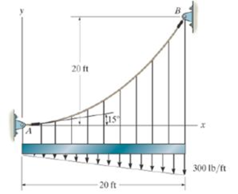
Chapter 7.4, Problem 111P
Determine the maximum tension developed in the cable if it is subjected to the triangular distributed load.
Prob. 7–111
Expert Solution & Answer
Want to see the full answer?
Check out a sample textbook solution
Students have asked these similar questions
Correct answer and complete fbd only. I will upvote.
A flanged bolt coupling consists of two concentric rows of bolts. The inner row has 6 nos. of 16mm diameterbolts spaced evenly in a circle of 250mm in diameter. The outer row of has 10 nos. of 25 mm diameter bolts spaced evenly in a circle of 500mm in diameter. If the allowable shear stress on one bolt is 60 MPa, determine the torque capacity of the coupling. The Poisson’s ratio of the inner row of bolts is 0.2 while that of the outer row is 0.25 and the bolts are steel, E =200 GPa.
Correct answer and complete fbd only. I will upvote.
10: The constant wall thickness of a steel tube with the cross sectionshown is 2 mm. If a 600-N-m torque is applied to the tube. Use G = 80 GPa forsteel.1. Find the shear stress (MPa) in the wall of the tube.2. Find the angle of twist, in degrees per meter of length.
CORRECT ANSWER WITH COMPLETE FBD ONLY. I WILL UPVOTE.
A torque wrench is used to tighten the pipe shown.Dimensions: S1 = 400 mm; S2 = 250 mm; S3 = 100 mmModulus of Rigidity G = 78 GPa1. The diameter of the solid pipe is 20 mm. How much is themaximum force P (N) that can be applied based on theallowable shear stress of 60 MPa?2. For a hollow pipe with 50 mm outside diameter and is 6 mmthick, compute for the maximum force P (kN) that can beapplied such that the angle of twist at A does not exceed 5degrees.3. The torque applied to tighten the hollow pipe is 200 N-m.Given: Pipe outside diameter = 50 mm Pipe thickness = 6 mmSolve for the resulting maximum shear stress (MPa) in the pipe.
Chapter 7 Solutions
ENGINEERING MECHANICS Â?? STATICS
Ch. 7.1 - In each case, calculate the reaction at A and then...Ch. 7.1 - Determine the normal force, shear force, and...Ch. 7.1 - Determine the normal force, shear force, and...Ch. 7.1 - Determine the normal force, shear force, and...Ch. 7.1 - Determine the normal force, shear force, and...Ch. 7.1 - Determine the normal force, shear force, and...Ch. 7.1 - Assume A is pinned and B is a roller. Prob. F7-6Ch. 7.1 - Determine the shear force and moment at points C...Ch. 7.1 - Assume the support at B is a roller. Point C is...Ch. 7.1 - Determine the internal normal force, shear force,...
Ch. 7.1 - Determine the internal normal force, shear force,...Ch. 7.1 - If a force of 20 lb is applied to the handles,...Ch. 7.1 - Determine the distance a as a fraction of the...Ch. 7.1 - Determine the internal shear force and moment...Ch. 7.1 - Determine the internal shear force and moment...Ch. 7.1 - Take P = 8 kN. Prob. 7-9Ch. 7.1 - Determine the largest vertical load P the frame...Ch. 7.1 - Determine the internal normal force, shear force,...Ch. 7.1 - Determine the distance a between the bearings in...Ch. 7.1 - Point D is located just to the left of the 5-kip...Ch. 7.1 - The shaft is supported by a journal bearing at A...Ch. 7.1 - Determine the internal normal force, shear force,...Ch. 7.1 - Determine the internal normal force, shear force,...Ch. 7.1 - Determine the normal force, shear force, and...Ch. 7.1 - Determine the internal normal force, shear force,...Ch. 7.1 - Prob. 19PCh. 7.1 - Determine the internal normal force, shear force,...Ch. 7.1 - Point E is located just to the left of 800 N...Ch. 7.1 - Point D is located just to the left of the roller...Ch. 7.1 - Determine the internal normal force, shear force,...Ch. 7.1 - Determine the ratio of a/b for which the shear...Ch. 7.1 - Point E is just to the right of the 3-kip load....Ch. 7.1 - Determine the internal normal force, shear force,...Ch. 7.1 - Determine the internal normal force, shear force,...Ch. 7.1 - Point D is located just to the left of the 10-kN...Ch. 7.1 - Determine the normal force, shear force, and...Ch. 7.1 - Determine the normal force, shear force, and...Ch. 7.1 - Determine the internal normal force, shear force,...Ch. 7.1 - Determine the internal normal force, shear force,...Ch. 7.1 - Determine the internal normal force, shear force,...Ch. 7.1 - Determine the internal normal force, shear force,...Ch. 7.1 - If the suspended load has a weight of 2 kN and a...Ch. 7.1 - Determine the internal normal force, shear force,...Ch. 7.1 - Determine the internal normal force, shear force,...Ch. 7.1 - Determine the internal normal force, shear force,...Ch. 7.1 - The distributed loading W = W0 sin , measured per...Ch. 7.1 - Solve Prob. 7-39 for = 120. Probs. 739/40Ch. 7.1 - z components of force and moment at point C in the...Ch. 7.1 - Determine the x, y, z components of force and...Ch. 7.1 - Determine the x, y, z components of internal...Ch. 7.1 - Determine the x, y. z components of internal...Ch. 7.2 - Determine the shear and moment as a function of x,...Ch. 7.2 - Determine the shear and moment as a function of x,...Ch. 7.2 - Determine the shear and moment as a function of x,...Ch. 7.2 - Determine the shear and moment as a function of x,...Ch. 7.2 - Determine the shear and moment as a function of x,...Ch. 7.2 - Determine the shear and moment as a function of x,...Ch. 7.2 - Draw the shear and moment diagrams for the shaft...Ch. 7.2 - Draw the shear and moment diagrams for the beam...Ch. 7.2 - Draw the shear and moment diagrams for the beam...Ch. 7.2 - Draw the shear and moment diagrams for the...Ch. 7.2 - Draw the shear and moment diagrams of the beam (a)...Ch. 7.2 - If L = 9 m, the beam will fail when the maximum...Ch. 7.2 - Draw the shear and moment diagrams for the beam....Ch. 7.2 - Draw the shear and moment diagrams for the beam....Ch. 7.2 - Draw the shear and bending-moment diagrams for the...Ch. 7.2 - The shaft is supported by a smooth thrust bearing...Ch. 7.2 - Draw the shear and moment diagrams for the beam....Ch. 7.2 - Draw the shear and moment diagrams for the beam....Ch. 7.2 - Draw the shear and moment diagrams for the...Ch. 7.2 - Draw the shear and bending-moment diagrams for...Ch. 7.2 - Draw the shear and moment diagrams for the beam....Ch. 7.2 - The shaft is supported by a smooth thrust bearing...Ch. 7.2 - Draw the shear and moment diagrams for the beam....Ch. 7.2 - The beam will fail when the maximum internal...Ch. 7.2 - Draw the shear and moment diagrams for the beam....Ch. 7.2 - Draw the shear and moment diagrams for the beam....Ch. 7.2 - Draw the shear and moment diagrams for the beam....Ch. 7.2 - Draw the shear and moment diagrams for the beam....Ch. 7.2 - Determine the internal normal force, shear force,...Ch. 7.2 - The quarter circular rod lies in the horizontal...Ch. 7.2 - Express the internal shear and moment components...Ch. 7.3 - Draw the shear and moment diagrams for the beam....Ch. 7.3 - Draw the shear and moment diagrams for the beam....Ch. 7.3 - Draw the shear and moment diagrams for the beam....Ch. 7.3 - Draw the shear and moment diagrams for the beam....Ch. 7.3 - Draw the shear and moment diagrams for the beam....Ch. 7.3 - Draw the shear and moment diagrams for the beam....Ch. 7.3 - Draw the shear and moment diagrams for the beam....Ch. 7.3 - Draw the shear and moment diagrams for the beam....Ch. 7.3 - Draw the shear and moment diagrams for the beam....Ch. 7.3 - Draw the shear and moment diagrams for the...Ch. 7.3 - Draw the shear and moment diagrams for the beam....Ch. 7.3 - Draw the shear and moment diagrams for the beam....Ch. 7.3 - Draw the shear and moment diagrams for the beam....Ch. 7.3 - Draw the shear and moment diagrams for the beam....Ch. 7.3 - Draw the shear and moment diagrams for the beam....Ch. 7.3 - Draw the shear and moment diagrams for the shaft....Ch. 7.3 - Draw the shear and moment diagrams for the beam....Ch. 7.3 - The beam consists of three segments pin connected...Ch. 7.3 - Draw the shear and moment diagrams for the beam....Ch. 7.3 - Draw the shear and moment diagrams for the beam....Ch. 7.3 - Draw the shear and moment diagrams for the beam....Ch. 7.3 - Draw the shear and moment diagrams for the beam....Ch. 7.3 - Draw the shear and moment diagrams for the beam....Ch. 7.3 - Draw the shear and moment diagrams for the beam....Ch. 7.3 - Draw the shear and moment diagrams for the beam....Ch. 7.3 - Draw the shear and moment diagrams for the beam....Ch. 7.3 - Draw the shear and moment diagrams for the beam....Ch. 7.3 - Draw the shear and moment diagrams for the beam....Ch. 7.3 - Draw the shear and moment diagrams for the beam....Ch. 7.3 - Draw the shear and moment diagrams for the beam....Ch. 7.4 - The cable supports the three loads shown....Ch. 7.4 - The cable supports the three loads shown....Ch. 7.4 - Determine the tension in each segment of the cable...Ch. 7.4 - The cable supports the loading shown. Determine...Ch. 7.4 - The cable supports the loading shown. Determine...Ch. 7.4 - The cable supports the three loads shown....Ch. 7.4 - The cable supports the three loads shown....Ch. 7.4 - Determine the force P needed to hold the cable in...Ch. 7.4 - Determine the maximum uniform loading w, measured...Ch. 7.4 - The cable is subjected to a uniform loading of w =...Ch. 7.4 - The cable AB is subjected to a uniform loading of...Ch. 7.4 - Prob. 105PCh. 7.4 - If yB = 1.5 ft. determine the largest weight of...Ch. 7.4 - The cable supports a girder which weighs 850...Ch. 7.4 - Prob. 108PCh. 7.4 - If the pipe has a mass per unit length of 1500...Ch. 7.4 - Prob. 110PCh. 7.4 - Determine the maximum tension developed in the...Ch. 7.4 - Prob. 112PCh. 7.4 - The cable is subjected to the parabolic loading w...Ch. 7.4 - The power transmission cable weighs 10 lb/fl. If...Ch. 7.4 - The power transmission cable weighs 10 lb/ft. If h...Ch. 7.4 - The man picks up the 52-ft chain and holds it just...Ch. 7.4 - Prob. 117PCh. 7.4 - Prob. 118PCh. 7.4 - Prob. 119PCh. 7.4 - A telephone line (cable) stretches between two...Ch. 7.4 - Prob. 121PCh. 7.4 - Prob. 122PCh. 7.4 - A cable has a weight of 5 lb/ft. If it can span...Ch. 7.4 - Prob. 124PCh. 7.4 - Determine the internal normal force, shear force,...Ch. 7.4 - Determine the normal force, shear force, and...Ch. 7.4 - Draw the shear and moment diagrams for the beam....Ch. 7.4 - Draw the shear and moment diagrams for the beam....Ch. 7.4 - Draw the shear and moment diagrams for the beam....Ch. 7.4 - Prob. 6RP
Knowledge Booster


Learn more about
Need a deep-dive on the concept behind this application? Look no further. Learn more about this topic, mechanical-engineering and related others by exploring similar questions and additional content below.Similar questions
- Correct answer and complete fbd only. I will upvote. 6: The shaft carries a total torque T0 that is uniformly distributedover its length L. Determine the angle of twist (degrees) of the shaft in termsif T0 = 1.2 kN-m, L = 2 m, G = 80 GPa, and diameter = 120 mm.arrow_forward2. Calculate the force in all members of the trusses shown using the method of joints. A 5525 lb C 3500 lb BY 14'-0" D 10'- 0" 6250 lb 10'- 0" Earrow_forwardCorrect answer and complete fbd only. I will upvote. 8: The steel rod fits loosely inside the aluminum sleeve. Both components are attached to a rigid wall at A andjoined together by a pin at B. Because of a slight misalignmentof the pre-drilled holes, the torque T0 = 750 N-m was appliedto the steel rod before the pin could be inserted into theholes. Determine the torque (N-m) in each component afterT0 was removed. Use G = 80 GPa for steel and G = 28 GPa foraluminumarrow_forward
- Correct answer and complete fbd only. I will upvote. 9: The two steel shafts, each with one end builtinto a rigid support, have flanges attached to their freeends. The flanges are to be bolted together. However,initially there is a 6⁰ mismatch in the location of the boltholes as shown in the figure. Determine the maximumshear stress(ksi) in each shaft after the flanges have beenbolted together. The shear modulus of elasticity for steelis 12 x 106 psi. Neglect deformations of the bolts and theflanges.arrow_forwardCorrect answer and complete fbd only. I will upvote. The tapered, wrought iron shaft carriesthe torque T = 2000 lb-in at its free end. Determine theangle of twist (degrees) of the shaft. Use G = 10 x 106psi for wrought ironarrow_forwardCorrect answer and complete fbd only. I will upvote. The compound shaft, consisting of steel and aluminumsegments, carries the two torques shown in the figure. Determine themaximum permissible value of T subject to the following designconditions: τst ≤ 83 MPa, τal ≤ 55 MPa, and θ ≤ 6⁰ (θ is the angle ofrotation of the free end). Use G =83 GPa for steel and G = 28 GPa foraluminum.arrow_forward
- The solid compound shaft, made of threedifferent materials, carries the two torques shown. Theshear moduli are 28 GPa for aluminum, 83 GPa for steel,and 35 GPa for bronze.1. Calculate the maximum shear stress (MPa) in eachmaterial.2. Find the angle of rotation (degrees) of the free endof the shaft.arrow_forwardCorrect answer only please. I will upvote. The velocity of a particle moves along the x-axis and is given by the equation ds/dt = 40 - 3t^2 m/s. Calculate the acceleration at time t=2 s and t=4 s. Calculate also the total displacement at the given interval. Assume at t=0 s=5m.Write the solution using pen and draw the graph if needed.arrow_forwardI want the steps of operation of the circuit, clearly in detail. Please. LV1arrow_forward
- Complet the solution: Vavg Ti Te Ts Qhexp Nuexp htheo Re Nutheo Error (m/s) (°C) (°C) (°C) (W) 2.11 18.8 21.3 45.8 2.61 18.5 20.8 46.3 Heat transfer Given data: a= 10 cm. L= 10 cm. b= 20 cm. H=40cm. ⚫ a = 10, cm: This could represent the width of the duct. ⚫b=20, cm: This might be the height of the duct. ⚫L = 10, cm: This usually stands for the length of the duct in the direction of flow. ⚫H=40, cm: This could indicate the height of some component or another duct-related dimension, but the exact meaning depends on the experiment's context.arrow_forwardplease explain each step and include drawings on the phase diagram. thanksarrow_forwardWrite clearly which points correspond to concentration of solute in front of alpha, concentration of solute in front of beta, amount of solid in the liquid in front of alpha/beta, lowest possible energy (tangent), as well as any other important information. Thank youarrow_forward
arrow_back_ios
SEE MORE QUESTIONS
arrow_forward_ios
Recommended textbooks for you
 Elements Of ElectromagneticsMechanical EngineeringISBN:9780190698614Author:Sadiku, Matthew N. O.Publisher:Oxford University Press
 Mechanics of Materials (10th Edition)Mechanical EngineeringISBN:9780134319650Author:Russell C. HibbelerPublisher:PEARSON
 Thermodynamics: An Engineering ApproachMechanical EngineeringISBN:9781259822674Author:Yunus A. Cengel Dr., Michael A. BolesPublisher:McGraw-Hill Education
 Control Systems EngineeringMechanical EngineeringISBN:9781118170519Author:Norman S. NisePublisher:WILEY
 Mechanics of Materials (MindTap Course List)Mechanical EngineeringISBN:9781337093347Author:Barry J. Goodno, James M. GerePublisher:Cengage Learning
 Engineering Mechanics: StaticsMechanical EngineeringISBN:9781118807330Author:James L. Meriam, L. G. Kraige, J. N. BoltonPublisher:WILEY
Elements Of Electromagnetics
Mechanical Engineering
ISBN:9780190698614
Author:Sadiku, Matthew N. O.
Publisher:Oxford University Press
Mechanics of Materials (10th Edition)
Mechanical Engineering
ISBN:9780134319650
Author:Russell C. Hibbeler
Publisher:PEARSON
Thermodynamics: An Engineering Approach
Mechanical Engineering
ISBN:9781259822674
Author:Yunus A. Cengel Dr., Michael A. Boles
Publisher:McGraw-Hill Education
Control Systems Engineering
Mechanical Engineering
ISBN:9781118170519
Author:Norman S. Nise
Publisher:WILEY
Mechanics of Materials (MindTap Course List)
Mechanical Engineering
ISBN:9781337093347
Author:Barry J. Goodno, James M. Gere
Publisher:Cengage Learning
Engineering Mechanics: Statics
Mechanical Engineering
ISBN:9781118807330
Author:James L. Meriam, L. G. Kraige, J. N. Bolton
Publisher:WILEY
Types Of loads - Engineering Mechanics | Abhishek Explained; Author: Prime Course;https://www.youtube.com/watch?v=4JVoL9wb5yM;License: Standard YouTube License, CC-BY