
ENGINEERING MECHANICS Â?? STATICS
15th Edition
ISBN: 9780137519132
Author: HIBBELER
Publisher: PEARSON
expand_more
expand_more
format_list_bulleted
Concept explainers
Videos
Textbook Question
Chapter 7.1, Problem 10P
Determine the largest vertical load P the frame will support and calculate the internal normal force, shear force, and moment at a section passing through point C for this loading.
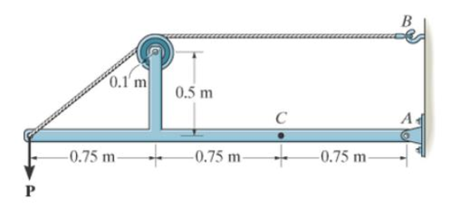
Prob. 7-10
Expert Solution & Answer
Want to see the full answer?
Check out a sample textbook solution
Students have asked these similar questions
A tensile specimen made of hot-rolled AISI 1020 steel is loaded to point corresponding to a strain of 43%.
60
Su = 66 ksi
Stress σ (ksi)
40 B
20
0
0
0
T
H
Sy = 39 ksi
Se = 36 ksi
Hot-rolled 1020 steel
F
10 20 30 40
50 60 70 80 90 100 110 120 130 140 150 160
Strain € (%)
T
1.1 1.2 1.3 1.4 1.5 1.6 1.7 1.8 1.9 2.0 2.1 2.2 2.3 2.4 2.5 2.6
Area ratio R
0.1
0.2
0.3
0.4
0.5
Area reduction A,
What value of strain is applicable to this location?
0.6
A tensile specimen made of hot-rolled AISI 1020 steel is loaded to point corresponding to a strain of 40%.
60
Su = 66 ksi
Stress σ (ksi)
S₁ = 39 ksi
40
Se = 36 ksi
Hot-rolled 1020 steel
20
0
10 20 30 40
50 60 70 80 90 100 110 120 130 140 150 160
Strain € (%)
0
1.1 1.2 1.3 1.4 1.5
1.6 1.7 1.8 1.9 2.0 2.1 2.2 2.3 2.4 2.5 2.6
Area ratio R
0.1
0.2
0.3
0.4
0.5
Area reduction A,
What value of area ratio is applicable to this location?
0.6
A tensile specimen made of hot-rolled AISI 1020 steel is loaded to point corresponding to a strain of 43%.
60
Su = 66 ksi
Stress σ (ksi)
20
Sy = 39 ksi
Se = 36 ksi
Hot-rolled 1020 steel
F
0
10 20 30
40 50 60
70 80 90 100 110 120 130 140 150 160
Strain € (%)
0
1.1 1.2 1.3 1.4 1.5 1.6 1.7 1.8 1.9 2.0 2.1 2.2 2.3 2.4 2.5 2.6
Area ratio R
0.1
0.2
0.3
0.4
0.5
Area reduction A,
What value of area reduction is applicable to this location?
0.6
Chapter 7 Solutions
ENGINEERING MECHANICS Â?? STATICS
Ch. 7.1 - In each case, calculate the reaction at A and then...Ch. 7.1 - Determine the normal force, shear force, and...Ch. 7.1 - Determine the normal force, shear force, and...Ch. 7.1 - Determine the normal force, shear force, and...Ch. 7.1 - Determine the normal force, shear force, and...Ch. 7.1 - Determine the normal force, shear force, and...Ch. 7.1 - Assume A is pinned and B is a roller. Prob. F7-6Ch. 7.1 - Determine the shear force and moment at points C...Ch. 7.1 - Assume the support at B is a roller. Point C is...Ch. 7.1 - Determine the internal normal force, shear force,...
Ch. 7.1 - Determine the internal normal force, shear force,...Ch. 7.1 - If a force of 20 lb is applied to the handles,...Ch. 7.1 - Determine the distance a as a fraction of the...Ch. 7.1 - Determine the internal shear force and moment...Ch. 7.1 - Determine the internal shear force and moment...Ch. 7.1 - Take P = 8 kN. Prob. 7-9Ch. 7.1 - Determine the largest vertical load P the frame...Ch. 7.1 - Determine the internal normal force, shear force,...Ch. 7.1 - Determine the distance a between the bearings in...Ch. 7.1 - Point D is located just to the left of the 5-kip...Ch. 7.1 - The shaft is supported by a journal bearing at A...Ch. 7.1 - Determine the internal normal force, shear force,...Ch. 7.1 - Determine the internal normal force, shear force,...Ch. 7.1 - Determine the normal force, shear force, and...Ch. 7.1 - Determine the internal normal force, shear force,...Ch. 7.1 - Prob. 19PCh. 7.1 - Determine the internal normal force, shear force,...Ch. 7.1 - Point E is located just to the left of 800 N...Ch. 7.1 - Point D is located just to the left of the roller...Ch. 7.1 - Determine the internal normal force, shear force,...Ch. 7.1 - Determine the ratio of a/b for which the shear...Ch. 7.1 - Point E is just to the right of the 3-kip load....Ch. 7.1 - Determine the internal normal force, shear force,...Ch. 7.1 - Determine the internal normal force, shear force,...Ch. 7.1 - Point D is located just to the left of the 10-kN...Ch. 7.1 - Determine the normal force, shear force, and...Ch. 7.1 - Determine the normal force, shear force, and...Ch. 7.1 - Determine the internal normal force, shear force,...Ch. 7.1 - Determine the internal normal force, shear force,...Ch. 7.1 - Determine the internal normal force, shear force,...Ch. 7.1 - Determine the internal normal force, shear force,...Ch. 7.1 - If the suspended load has a weight of 2 kN and a...Ch. 7.1 - Determine the internal normal force, shear force,...Ch. 7.1 - Determine the internal normal force, shear force,...Ch. 7.1 - Determine the internal normal force, shear force,...Ch. 7.1 - The distributed loading W = W0 sin , measured per...Ch. 7.1 - Solve Prob. 7-39 for = 120. Probs. 739/40Ch. 7.1 - z components of force and moment at point C in the...Ch. 7.1 - Determine the x, y, z components of force and...Ch. 7.1 - Determine the x, y, z components of internal...Ch. 7.1 - Determine the x, y. z components of internal...Ch. 7.2 - Determine the shear and moment as a function of x,...Ch. 7.2 - Determine the shear and moment as a function of x,...Ch. 7.2 - Determine the shear and moment as a function of x,...Ch. 7.2 - Determine the shear and moment as a function of x,...Ch. 7.2 - Determine the shear and moment as a function of x,...Ch. 7.2 - Determine the shear and moment as a function of x,...Ch. 7.2 - Draw the shear and moment diagrams for the shaft...Ch. 7.2 - Draw the shear and moment diagrams for the beam...Ch. 7.2 - Draw the shear and moment diagrams for the beam...Ch. 7.2 - Draw the shear and moment diagrams for the...Ch. 7.2 - Draw the shear and moment diagrams of the beam (a)...Ch. 7.2 - If L = 9 m, the beam will fail when the maximum...Ch. 7.2 - Draw the shear and moment diagrams for the beam....Ch. 7.2 - Draw the shear and moment diagrams for the beam....Ch. 7.2 - Draw the shear and bending-moment diagrams for the...Ch. 7.2 - The shaft is supported by a smooth thrust bearing...Ch. 7.2 - Draw the shear and moment diagrams for the beam....Ch. 7.2 - Draw the shear and moment diagrams for the beam....Ch. 7.2 - Draw the shear and moment diagrams for the...Ch. 7.2 - Draw the shear and bending-moment diagrams for...Ch. 7.2 - Draw the shear and moment diagrams for the beam....Ch. 7.2 - The shaft is supported by a smooth thrust bearing...Ch. 7.2 - Draw the shear and moment diagrams for the beam....Ch. 7.2 - The beam will fail when the maximum internal...Ch. 7.2 - Draw the shear and moment diagrams for the beam....Ch. 7.2 - Draw the shear and moment diagrams for the beam....Ch. 7.2 - Draw the shear and moment diagrams for the beam....Ch. 7.2 - Draw the shear and moment diagrams for the beam....Ch. 7.2 - Determine the internal normal force, shear force,...Ch. 7.2 - The quarter circular rod lies in the horizontal...Ch. 7.2 - Express the internal shear and moment components...Ch. 7.3 - Draw the shear and moment diagrams for the beam....Ch. 7.3 - Draw the shear and moment diagrams for the beam....Ch. 7.3 - Draw the shear and moment diagrams for the beam....Ch. 7.3 - Draw the shear and moment diagrams for the beam....Ch. 7.3 - Draw the shear and moment diagrams for the beam....Ch. 7.3 - Draw the shear and moment diagrams for the beam....Ch. 7.3 - Draw the shear and moment diagrams for the beam....Ch. 7.3 - Draw the shear and moment diagrams for the beam....Ch. 7.3 - Draw the shear and moment diagrams for the beam....Ch. 7.3 - Draw the shear and moment diagrams for the...Ch. 7.3 - Draw the shear and moment diagrams for the beam....Ch. 7.3 - Draw the shear and moment diagrams for the beam....Ch. 7.3 - Draw the shear and moment diagrams for the beam....Ch. 7.3 - Draw the shear and moment diagrams for the beam....Ch. 7.3 - Draw the shear and moment diagrams for the beam....Ch. 7.3 - Draw the shear and moment diagrams for the shaft....Ch. 7.3 - Draw the shear and moment diagrams for the beam....Ch. 7.3 - The beam consists of three segments pin connected...Ch. 7.3 - Draw the shear and moment diagrams for the beam....Ch. 7.3 - Draw the shear and moment diagrams for the beam....Ch. 7.3 - Draw the shear and moment diagrams for the beam....Ch. 7.3 - Draw the shear and moment diagrams for the beam....Ch. 7.3 - Draw the shear and moment diagrams for the beam....Ch. 7.3 - Draw the shear and moment diagrams for the beam....Ch. 7.3 - Draw the shear and moment diagrams for the beam....Ch. 7.3 - Draw the shear and moment diagrams for the beam....Ch. 7.3 - Draw the shear and moment diagrams for the beam....Ch. 7.3 - Draw the shear and moment diagrams for the beam....Ch. 7.3 - Draw the shear and moment diagrams for the beam....Ch. 7.3 - Draw the shear and moment diagrams for the beam....Ch. 7.4 - The cable supports the three loads shown....Ch. 7.4 - The cable supports the three loads shown....Ch. 7.4 - Determine the tension in each segment of the cable...Ch. 7.4 - The cable supports the loading shown. Determine...Ch. 7.4 - The cable supports the loading shown. Determine...Ch. 7.4 - The cable supports the three loads shown....Ch. 7.4 - The cable supports the three loads shown....Ch. 7.4 - Determine the force P needed to hold the cable in...Ch. 7.4 - Determine the maximum uniform loading w, measured...Ch. 7.4 - The cable is subjected to a uniform loading of w =...Ch. 7.4 - The cable AB is subjected to a uniform loading of...Ch. 7.4 - Prob. 105PCh. 7.4 - If yB = 1.5 ft. determine the largest weight of...Ch. 7.4 - The cable supports a girder which weighs 850...Ch. 7.4 - Prob. 108PCh. 7.4 - If the pipe has a mass per unit length of 1500...Ch. 7.4 - Prob. 110PCh. 7.4 - Determine the maximum tension developed in the...Ch. 7.4 - Prob. 112PCh. 7.4 - The cable is subjected to the parabolic loading w...Ch. 7.4 - The power transmission cable weighs 10 lb/fl. If...Ch. 7.4 - The power transmission cable weighs 10 lb/ft. If h...Ch. 7.4 - The man picks up the 52-ft chain and holds it just...Ch. 7.4 - Prob. 117PCh. 7.4 - Prob. 118PCh. 7.4 - Prob. 119PCh. 7.4 - A telephone line (cable) stretches between two...Ch. 7.4 - Prob. 121PCh. 7.4 - Prob. 122PCh. 7.4 - A cable has a weight of 5 lb/ft. If it can span...Ch. 7.4 - Prob. 124PCh. 7.4 - Determine the internal normal force, shear force,...Ch. 7.4 - Determine the normal force, shear force, and...Ch. 7.4 - Draw the shear and moment diagrams for the beam....Ch. 7.4 - Draw the shear and moment diagrams for the beam....Ch. 7.4 - Draw the shear and moment diagrams for the beam....Ch. 7.4 - Prob. 6RP
Knowledge Booster


Learn more about
Need a deep-dive on the concept behind this application? Look no further. Learn more about this topic, mechanical-engineering and related others by exploring similar questions and additional content below.Similar questions
- Table of Measurements and Results: Reading m/s Ji- a (wh Nu h Re Nu Error% (C) (°C) 2 1 Discussion: 1-Estimate the heat transfer and experimental value of the heat transfer coefficient hex with its unit and Nusselt number Nu expl 2- Find the percentage error for the value of the experimental Nusselt number. 3-Draw the graph showing a relationship between the temperatures difference (T-T) and theoretical and experimental value of Nusselt number. 4-The forced convection heat transfer coefficient of a plate depends on which of the following: a-gravity. b-velocity of fluid. e-conductivity of fluid. d-conductivity of plate material. Experiment: Internal Forced convenction Heat trovate on now through t objectives. Study the convection heat transfer of air flow through stage Calculations. Q & (T-T) Vary Re Q. heup A (TT) (T. Te-T ASPL Nep Re 117 RITT 14 ' 14arrow_forwardIf AE = 1.6 m, ED = CD = 1.9 m and F = 3.1 kN, then find the magnitude of the force acting in EB. B 30° 30° C E D ED m DC m ♥F KNarrow_forwardAssume multiple single degree of freedom systems with natural periods T ∈ [0.05, 2.00] seconds with in- crement of period dT = 0.05 seconds. Assume three cases of damping ratio: Case (A) ξ = 0%; Case (B) ξ = 2%; Case (C) ξ = 5%. The systems are initially at rest. Thus, the initial conditions are u(t = 0) = 0 and ̇u(t = 0) = 0. The systems are subjected to the base acceleration that was provided in the ElCentro.txt file (i.e., first column). For the systems in Case (A), Case (B), and Case (C) and for each natural period compute the peak acceleration, peak velocity, and peak displacement responses to the given base excitation. Please, use the Newmark method for β = 1/4 (average acceleration) to compute the responses. Create three plots with three lines in each plot. The first plot will have the peak accelerations in y-axis and the natural period of the system in x-axis. The second plot will have the peak velocities in y-axis and the natural period of the system in x-axis. The third plot…arrow_forward
- Determine the resultant stress at points P and Q.arrow_forwardFor the notched specimen with h = 0.13 m and r =11 mm, calculate the nominal stress for F=5 kN. F h F 25 mm Please submit your answer in the units of MPa.arrow_forwardA tensile specimen made of hot-rolled AISI 1020 steel is loaded to point corresponding to a strain of 49%. 60 Su = 66 ksi Stress σ (ksi) Sy = 39 ksi 400B Se = 36 ksi Hot-rolled 1020 steel 20 F 0 0 10 20 30 40 50 60 70 80 90 100 110 120 130 140 150 160 Strain € (%) 0 1.1 1.2 1.3 1.4 1.5 1.6 1.7 1.8 1.9 2.0 2.1 2.2 2.3 2.4 2.5 2.6 Area ratio R 0.1 0.2 0.3 0.4 0.5 Area reduction A, What value of Su is applicable to this location? 0.6arrow_forward
- A tensile specimen made of hot-rolled AISI 1020 steel is loaded to point corresponding to a strain of 40%. 60 Su = 66 ksi Stress σ (ksi) 40 20 Sy= = 39 ksi Se = 36 ksi Hot-rolled 1020 steel F | G | H 0 10 20 30 40 50 60 0 70 80 90 100 110 120 130 140 150 160 Strain € (%) ☐ T 1.1 1.2 1.3 1.4 1.5 1.6 1.7 1.8 1.9 2.0 2.1 2.2 2.3 2.4 2.5 2.6 Area ratio R 0.1 0.2 0.3 0.4 0.5 Area reduction A, What value of Sy is applicable to this location? 0.6arrow_forwardA vertical .2m by .2m square plate is exposed to saturated water vapor at atmospheric pressure. If the surface temperature is 80 degrees C and the flow is laminar, estimate the loal heat transfer coefficents at the middles and at the bottom of the plate.arrow_forwardA transformer that is 10 cm long, 6.2 cm wide, and 5 cm high is to be cooled by attaching a 10 cm by 6.2 cm wide polished aluminum heat sink(emissivity=.03) to its top surface. The heat sink has seven fins, which are 5 mm high, 2mm thick, and 10 cm long. A fan blows air at 25 degrees C parallel to the passages between the fins. The heat sink is to dissipate 12W of heat, and the base temp of the ehat sink is not to exceed 60 degrees C. Assuming the fins and the base plate to be nearly isothermal and the radiation heat transfer to be negligible, determine the minimum free-stream velocity the fan needs to supply to avoid overheating. Assume the flow is laminar over the entire finned surface of the transformer.arrow_forward
- I need a mechanical engineering expert to solve this question,no Ai pleasearrow_forwardCan you give me the meaning of Combination spanner and Give Examples of Spannersarrow_forwardHW8 A shaft fitted with a flywheel rotates at 650 r.p.m. and drives a machine. The torque of machine varies in a cyclic manner over a period of 2 revolutions. The torque rises from 650 N-m to 2200 N-m uniformly during 110° and remains constant for the following 270°. It then falls uniformly to 600 N-m during the next 100° and remains constant for the end cycle, the cycle being repeated thereafter. Determine the power required to drive the machine and percentage fluctuation in speed, if the driving torque applied to the shaft is constant and the mass of the flywheel is 180 kg with radius of gyration of 35 cm. HW9arrow_forward
arrow_back_ios
SEE MORE QUESTIONS
arrow_forward_ios
Recommended textbooks for you
 Elements Of ElectromagneticsMechanical EngineeringISBN:9780190698614Author:Sadiku, Matthew N. O.Publisher:Oxford University Press
 Mechanics of Materials (10th Edition)Mechanical EngineeringISBN:9780134319650Author:Russell C. HibbelerPublisher:PEARSON
 Thermodynamics: An Engineering ApproachMechanical EngineeringISBN:9781259822674Author:Yunus A. Cengel Dr., Michael A. BolesPublisher:McGraw-Hill Education
 Control Systems EngineeringMechanical EngineeringISBN:9781118170519Author:Norman S. NisePublisher:WILEY
 Mechanics of Materials (MindTap Course List)Mechanical EngineeringISBN:9781337093347Author:Barry J. Goodno, James M. GerePublisher:Cengage Learning
 Engineering Mechanics: StaticsMechanical EngineeringISBN:9781118807330Author:James L. Meriam, L. G. Kraige, J. N. BoltonPublisher:WILEY
Elements Of Electromagnetics
Mechanical Engineering
ISBN:9780190698614
Author:Sadiku, Matthew N. O.
Publisher:Oxford University Press
Mechanics of Materials (10th Edition)
Mechanical Engineering
ISBN:9780134319650
Author:Russell C. Hibbeler
Publisher:PEARSON
Thermodynamics: An Engineering Approach
Mechanical Engineering
ISBN:9781259822674
Author:Yunus A. Cengel Dr., Michael A. Boles
Publisher:McGraw-Hill Education
Control Systems Engineering
Mechanical Engineering
ISBN:9781118170519
Author:Norman S. Nise
Publisher:WILEY
Mechanics of Materials (MindTap Course List)
Mechanical Engineering
ISBN:9781337093347
Author:Barry J. Goodno, James M. Gere
Publisher:Cengage Learning
Engineering Mechanics: Statics
Mechanical Engineering
ISBN:9781118807330
Author:James L. Meriam, L. G. Kraige, J. N. Bolton
Publisher:WILEY
Understanding Shear Force and Bending Moment Diagrams; Author: The Efficient Engineer;https://www.youtube.com/watch?v=C-FEVzI8oe8;License: Standard YouTube License, CC-BY
Bending Stress; Author: moodlemech;https://www.youtube.com/watch?v=9QIqewkE6xM;License: Standard Youtube License