
Concept explainers
Videos
(a)
Calculate the energy stored in each energy storage element.
(a)
Answer to Problem 70E
The value of energy stored in the inductor
Explanation of Solution
Given data:
Refer to Figure 7.84 in the textbook.
Calculation:
The given circuit is redrawn as shown in Figure 1.
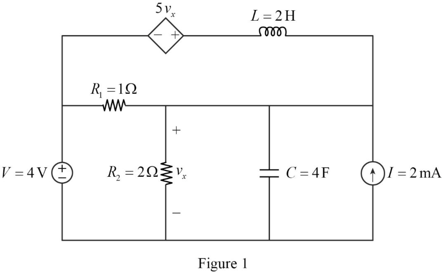
For a DC circuit, at steady state condition, the capacitor acts like open circuit and the inductor acts like short circuit.
Now, the Figure 1 is reduced as shown in Figure 2.
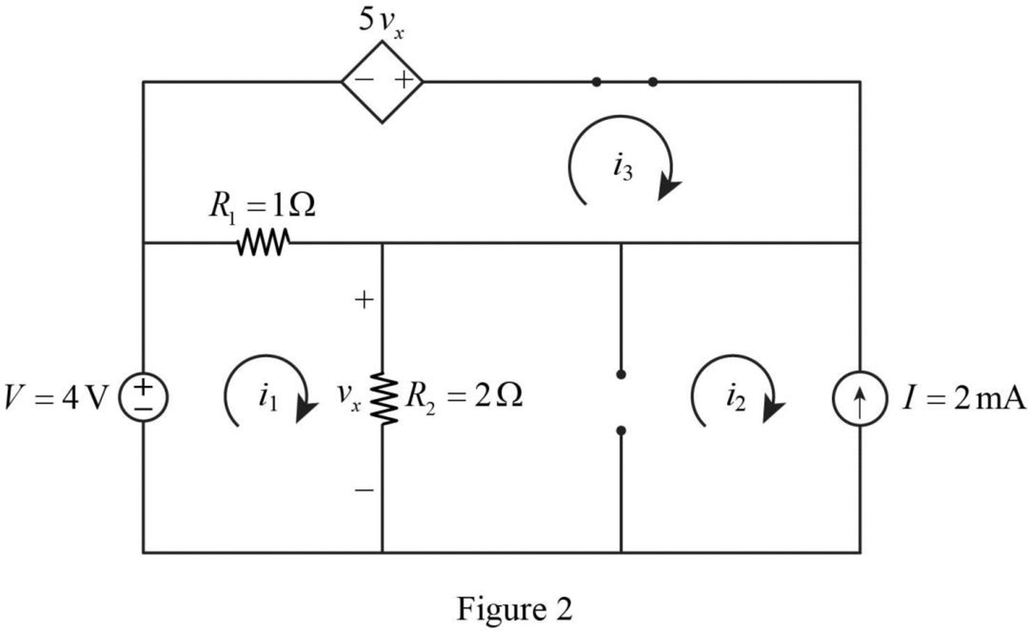
Apply Kirchhoff’s voltage law for loop 1 in Figure 2.
Refer to Figure 2, the current
Substitute
Simplify the above equation to find
Apply Kirchhoff’s voltage law for loop 3 in Figure 2.
Refer to Figure 2, the voltage across the resistor
The voltage
Substitute equation (4) in (3).
Substitute
Substitute equation (2) in (5).
Simplify the above equation to find
Substitute
Refer to Figure 2, the current
Substitute
Refer to Figure 2, the resistor
Write a general expression to calculate the energy stored in a inductor.
Here,
Write a general expression to calculate the energy stored in a capacitor.
Here,
Substitute
Simplify the above equation to find
Substitute
Simplify the above equation to find
Conclusion:
Thus, the value of energy stored in the inductor
(b)
Verify the calculated answers with an appropriate simulation.
(b)
Explanation of Solution
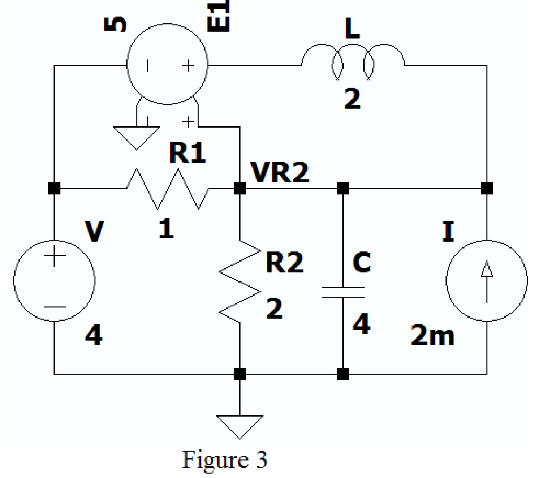
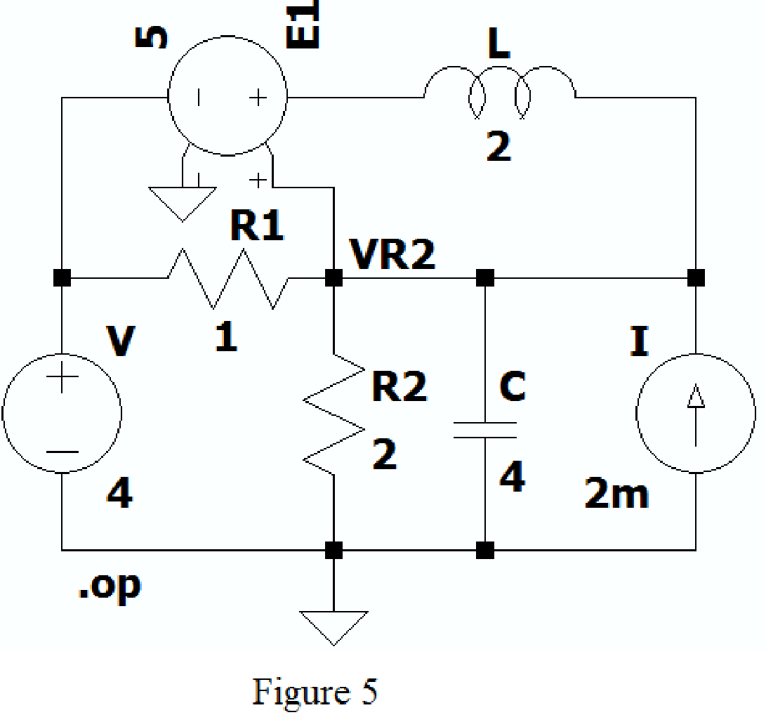
Create the new schematic in LTspice and draw the Figure 1 as shown in Figure 3. Use the Label net option and write VR2 to find voltage across resistor
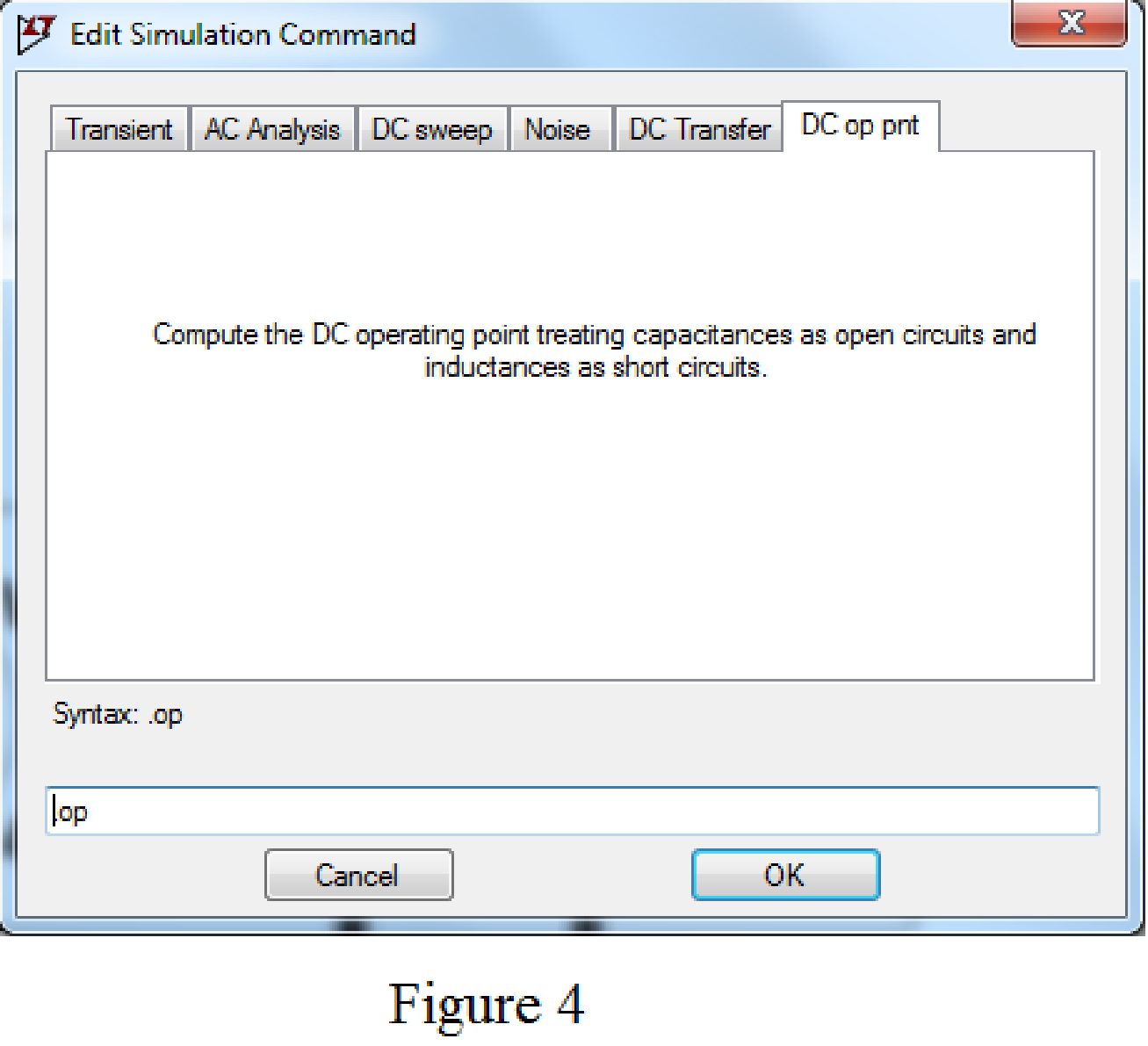
Choose the Dc op point in Edit simulation Cmd as shown in Figure 4.
After adding the above mentioned commands the circuit becomes as shown in Figure 5.
Now run the simulation, the table will be displayed with the values of current through resistors, capacitor and voltage across the capacitor as shown in Figure 6.
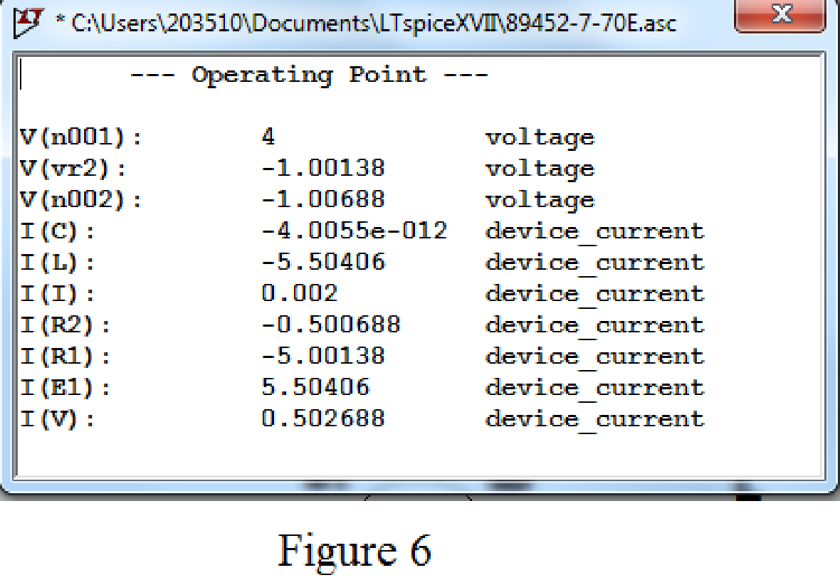
Refer to Figure 6, the value of voltage across the capacitor
Conclusion:
Thus, the calculated answers are verified with an appropriate SPICE simulation.
Want to see more full solutions like this?
Chapter 7 Solutions
ENGINEERING CIRCUIT...(LL)>CUSTOM PKG.<


- Q1. Consider the unity feedback control system whose open-loop transfer function is: G(s): = 40(S+2) s(s+3)(s+1)(s + 10) ELECTRIC Ziegler-Nichols, By using second method of Ziegler- Nichols, calculate the PID, PI-D and I-PD parameters and make tuning for this parameters to get accepting response for the following system, then comp controllers? PARTME then compare your results for all types GINEARIarrow_forwardI need solution by hand plzarrow_forwardPlease solve this circuit using Laplace Transform, show proper solution.arrow_forward
- Please show step by step solution.arrow_forwardExample 1: There is a transfer function for a second-order system given as follows. 120 G(s)= s²+12s+120 Find 5,,, T, T, T., and %OS.arrow_forward5. Please sketch a root locus manually for the following system. R(s) + E(s) C(s) k(s + 1) s² + 2s +2 Each branch in your root locus must be labeled with an arrow. Please answer the following questions. a. Is the closed-loop system stable as k is varying from 0 to co? Please find an answer to this question via root locus. b. What are finite zeros and poles? Are there infinite zeros? If so, how many?arrow_forward
- -5. Draw the connection diagram for two parallel transformers with (A-A) connected?arrow_forwardHW_#6 HW_06.pdf EE 213-01 Assignments zm Rich LTI uah.instructure.com Z (MAE 272-01) (SP25) DYNAMICS b My Questions | bartleby ✓ Download → Info Page 1 > of 2 - ZOOM + 1) (5 pts) Note have to use nodal analysis at Vp and Vn. a) Determine Vout in the following ideal op-amp circuit. The power supplies supplying power to the op-amp have voltage values of ±15 volts (Vcc = +15 Volts, -VCC = -15Volts) b) Determine the value of RĘ that makes Vo, -15 Volts. c) What value of RF makes Vo = 0 Volts? out F out = 2V 1V 25K 10K 2V 1V 30K 100K RF 12K 12K + E น out E 2) (5 pts) Find Vout in the following circuit. Perform nodal analysis at nodes VN, VP and Va 20K Va 20K 10K 10K 1 V 2 V 5K Vout 15K Note: There is no restriction on the value for Vout for this problem. 3) (5 pts) For the Thevenin equivalent circuit shown, answer the following questions: 250 Ohms a 200 V ° b a) What load resistor results in maximum power delivered to that resistor? b) What is the maximum power delivered to the resistor in…arrow_forwardSuppose the Laplace transform of a causal signal x₁ (t) is given by X₁(s) s+2 s²+1 (a) What is the Fourier transform X₁ (w) of the signal? (b) Using the Laplace transform properties, find the Laplace transform of the following signal x2(t). x2(t) = e³ x₁(t−1)-4x₁(4) Note, you do not need to simplify the expression of X2(s). However, state whether it is possible to write X2(s) as a rational fraction (i.e. ratio of polynomials) in s.arrow_forward
- Consider the following mechanical system. In the figure, y(t) denotes the displacement of the mass from its equilibrium position and u(t) denotes the force applied to the mass. k1 kz - y(t) -0000 0000 3 ► u(t) b a) Find the differential equation model of the system. b) Find the state-space model for the system. Write x, A, B, C and D clearly in your answer.arrow_forwardSee whole documentarrow_forwardC(s) a) Reduce the following system to a single transfer function G(s): R(s) G3(s) R(s) C(s) G1(s) G2(s) G4(s) b) If the input r(t) is a step signal, what will be the output C(s)? Hint: Move the block G₂(s).arrow_forward
 Introductory Circuit Analysis (13th Edition)Electrical EngineeringISBN:9780133923605Author:Robert L. BoylestadPublisher:PEARSON
 Delmar's Standard Textbook Of ElectricityElectrical EngineeringISBN:9781337900348Author:Stephen L. HermanPublisher:Cengage Learning
 Programmable Logic ControllersElectrical EngineeringISBN:9780073373843Author:Frank D. PetruzellaPublisher:McGraw-Hill Education
 Fundamentals of Electric CircuitsElectrical EngineeringISBN:9780078028229Author:Charles K Alexander, Matthew SadikuPublisher:McGraw-Hill Education
 Electric Circuits. (11th Edition)Electrical EngineeringISBN:9780134746968Author:James W. Nilsson, Susan RiedelPublisher:PEARSON
 Engineering ElectromagneticsElectrical EngineeringISBN:9780078028151Author:Hayt, William H. (william Hart), Jr, BUCK, John A.Publisher:Mcgraw-hill Education,