
Concept explainers
Videos
(a)
Write the nodal equation of the circuit.
(a)
Answer to Problem 45E
The nodal equation of the circuit at node voltage
Explanation of Solution
Calculation:
The redrawn circuit is shown in Figure 1.
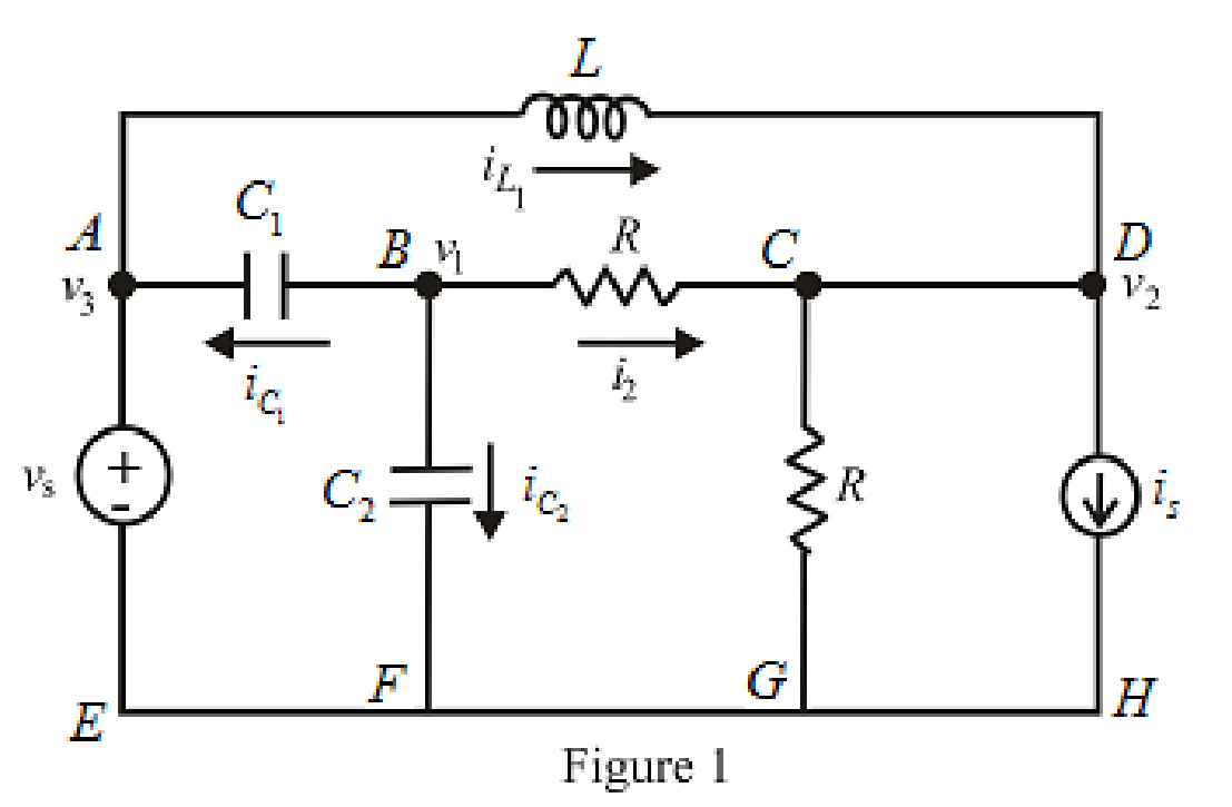
Here,
The expression for the current across the inductor is,
Here,
The expression for the current across capacitor is,
Here,
The expression for the nodal analysis at node
Rearrange equation (3),
The voltage at node voltage
Substitute
The expression for the nodal analysis at node voltage
The node voltage across resistance
Rearrange equation (7),
Conclusion:
Thus, the nodal equation of the circuit at node voltage
(b)
Write the mesh equation of the circuit.
(b)
Answer to Problem 45E
The mesh equation of the circuit in loop
Explanation of Solution
Calculation:
The redrawn circuit is shown in Figure 2 as follows,
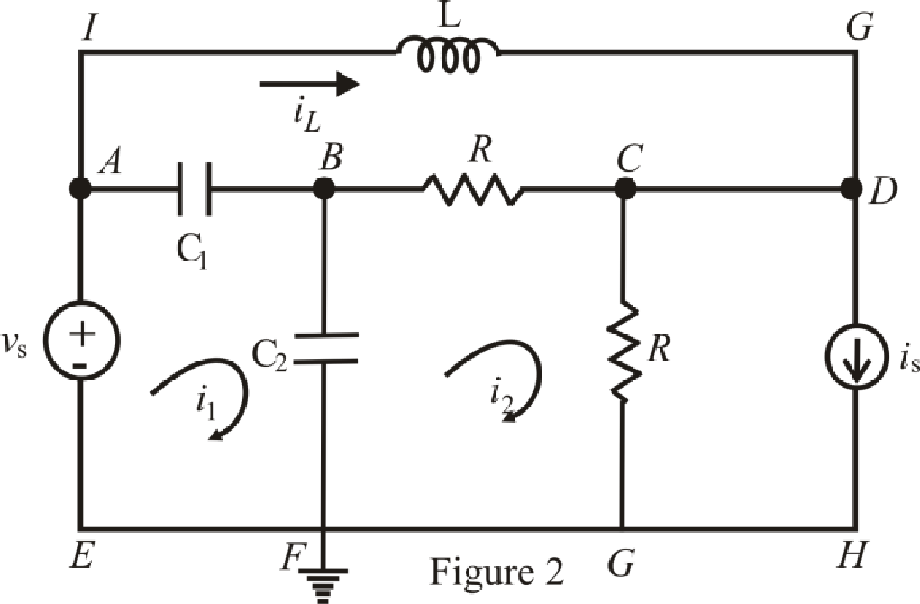
Refer to the Figure 2,
The voltage at node voltage
The expression for mesh equation in loop
Here,
Substitute
The expression for mesh equation in loop
Substitute
The expression for mesh equation in loop
Conclusion:
Thus, the mesh equation of the circuit in loop
Want to see more full solutions like this?
Chapter 7 Solutions
ENGINEERING CIRCUIT...(LL)>CUSTOM PKG.<


- Calculate the value for V1, V2 and V3arrow_forwardPrelab Information Laboratory Preliminary Discussion Second-order RLC Circuit Analysis The second-order RLC circuit shown in figure 1 below represents all voltages and impedances as functions of the complex variable, s. Note, of course, that the impedances associated with R, RL, and Rs are constant independent of frequency, so the 's' notation is omitted. Again, one of the advantages of s-domain analysis is that we can apply all of the circuit analysis techniques learned for AC and DC circuits. ZI(s) Zc(s) Rs w RL ww + + VRS(S) VRL(S) VL(s) Vc(s) VR(S) R Vs(s) Figure 1: A second-order RLC circuit represented in the s-domain. To generate the s-domain expression for the output voltage, Vout(s) = VR(S), for the circuit shown in figure 1, we can apply voltage division in the s-domain as shown in equation 1 below. For equation 1 we define the following circuit parameters. RT=RS + RL + R where: R₁ = Total series resistance Rs Signal generator output resistance (fixed) Inductor internal…arrow_forward5.137 The BJT in the circuit of Fig. 5.137 has ẞ = 100. (a) Find the de collector current and the de voltage at the collector. (b) Replacing the transistor by its T model, draw the small-signal equivalent circuit of the amplifier. Analyze the resulting circuit to determine the voltage gain vo/vi. V ww 0.3 mA 300 ΚΩ = 250 Ω Va 30 ΚΩ www|| Fig. 5.137arrow_forward
- solve this, show all steps, no ai pz, please draw it outarrow_forwardNO AI PLEASE WILL REJECTarrow_forward"?Can the expert help me solve only a bonus question using Arduino" The system must control 3 LEDs (Red, Green, and Blue) to operate in 4 different lighting modes: Mode 3: LEDs fade in and out smoothly (PWM control) in the order Red Green → Blue. Bonus Challenge (Potentiometer Control): The potentiometer (connected to pin A0) allows for dynamic control of the brightness during the fading mode (Mode 3). This allows the user to adjust how bright or dim the LEDs should fade in and out. This solution meets the project requirements, including the current limits, and provides interactive functionality with the push button and potentiometer.arrow_forward
 Introductory Circuit Analysis (13th Edition)Electrical EngineeringISBN:9780133923605Author:Robert L. BoylestadPublisher:PEARSON
 Delmar's Standard Textbook Of ElectricityElectrical EngineeringISBN:9781337900348Author:Stephen L. HermanPublisher:Cengage Learning
 Programmable Logic ControllersElectrical EngineeringISBN:9780073373843Author:Frank D. PetruzellaPublisher:McGraw-Hill Education
 Fundamentals of Electric CircuitsElectrical EngineeringISBN:9780078028229Author:Charles K Alexander, Matthew SadikuPublisher:McGraw-Hill Education
 Electric Circuits. (11th Edition)Electrical EngineeringISBN:9780134746968Author:James W. Nilsson, Susan RiedelPublisher:PEARSON
 Engineering ElectromagneticsElectrical EngineeringISBN:9780078028151Author:Hayt, William H. (william Hart), Jr, BUCK, John A.Publisher:Mcgraw-hill Education,