
Concept explainers
Videos
(a)
Find the energy stored in the element at time
(a)
Answer to Problem 68E
The energy stored in the element at time
Explanation of Solution
Given data:
Write a general expression to calculate the energy stored in an inductor.
Here,
Given data:
Refer to Figure 7.82 in the textbook.
The value of initial current through inductor
Calculation:
Substitute
Substitute
Simplify the above equation to find
Conclusion:
Thus, the energy stored in the element at time
(b)
Determine the value of
(b)
Answer to Problem 68E
The value of
Explanation of Solution
Calculation:
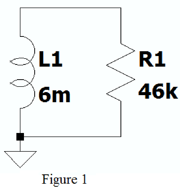
Create the new schematic in LTspice with series connected resistor and inductor of given circuit as shown in Figure 1.
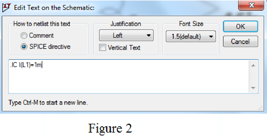
Using SPICE Directive mention the command .ic I(L1)=1m as shown in Figure 2.
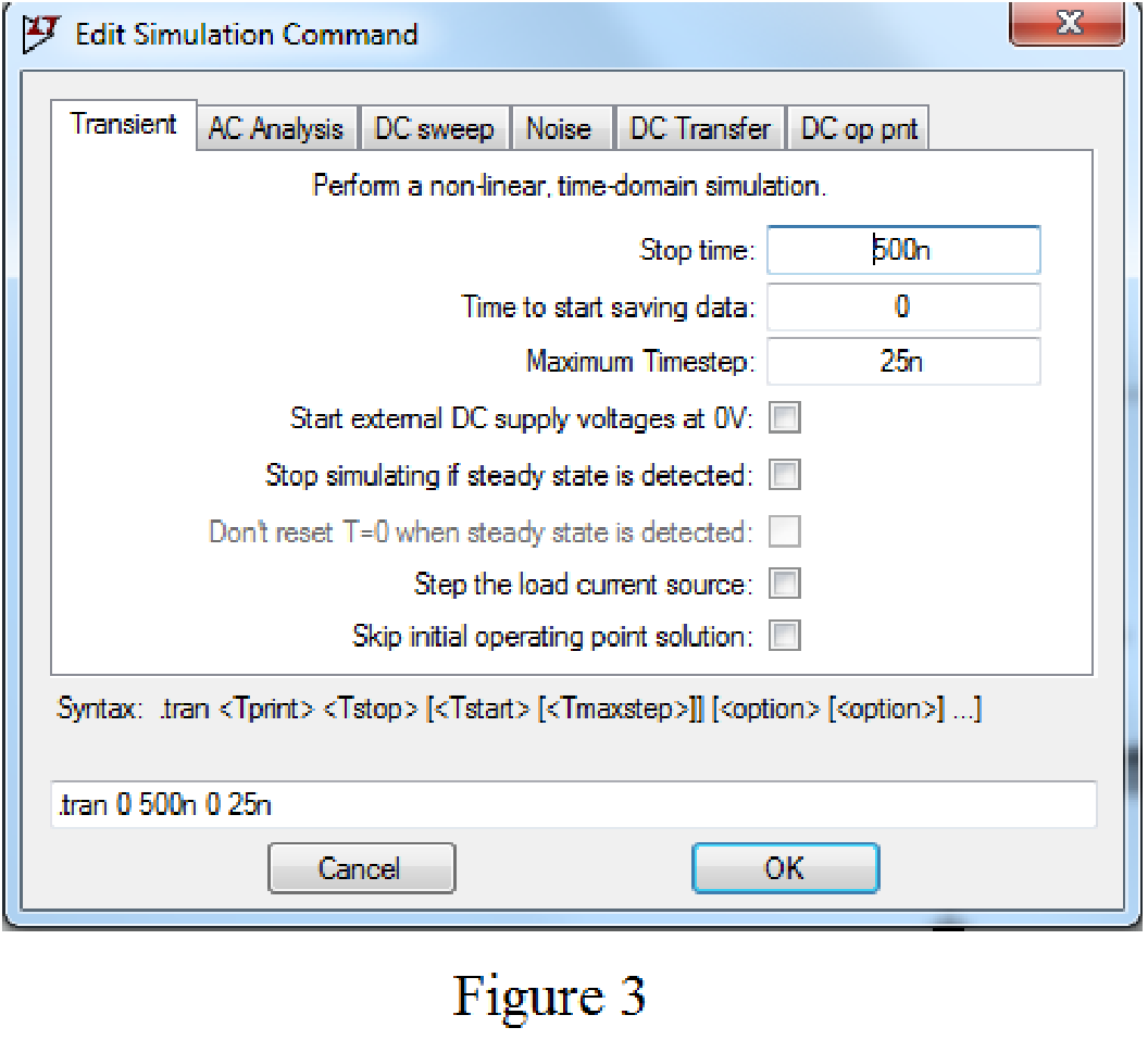
Enter the stop time as 500ns, time to start saving data as 0, and maximum Timestep as 25ns in Edit simulation Cmd as shown in Figure 3.
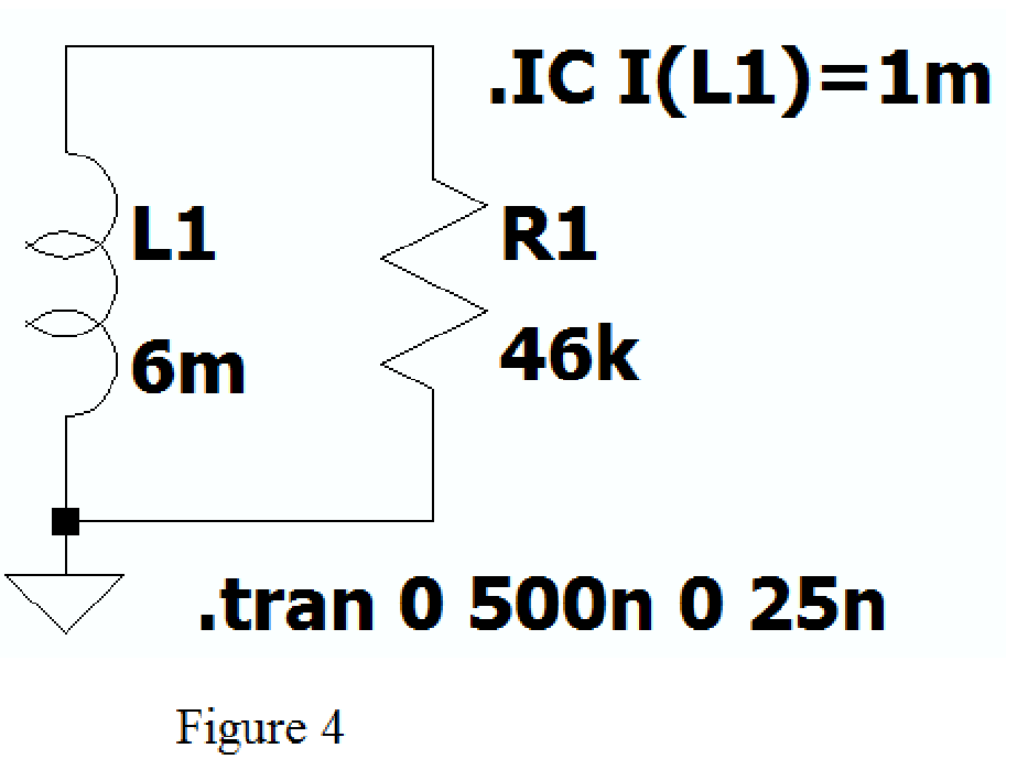
After adding the Spice directives the circuit shows as in Figure 4.
Now run the simulation and place the probe at inductor, the plot of the current through inductor with respect to time is shown as shown in Figure 5.
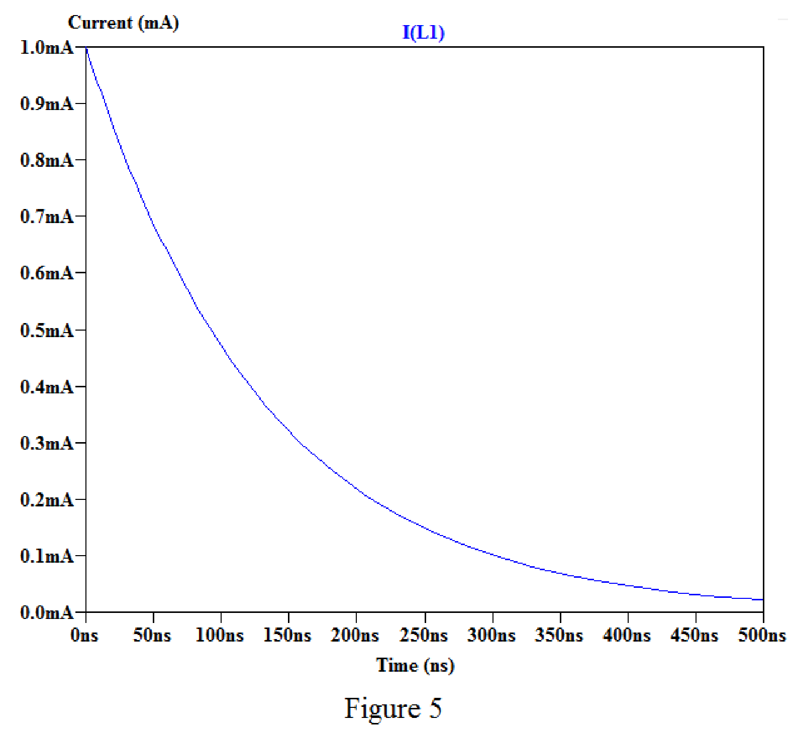
By placing the cursor on the graph, we obtain the current values for different time as shown in below.
For time
For time
For time
For time
Conclusion:
Thus, the value of
(c)
Find the value of initial energy remains in the inductor at time
(c)
Answer to Problem 68E
The value of initial energy remains in the inductor at time
Explanation of Solution
Calculation:
Refer to part (b), the value of current at time
Substitute
Substitute
Simplify the above equation to find
Substitute
Substitute
Simplify the above equation to find
Conclusion:
Thus, the value of initial energy remains in the inductor at time
Want to see more full solutions like this?
Chapter 7 Solutions
ENGINEERING CIRCUIT...(LL)>CUSTOM PKG.<


- HW_#6 HW_06.pdf EE 213-01 Assignments zm Rich LTI uah.instructure.com Z (MAE 272-01) (SP25) DYNAMICS b My Questions | bartleby ✓ Download → Info Page 1 > of 2 - ZOOM + 1) (5 pts) Note have to use nodal analysis at Vp and Vn. a) Determine Vout in the following ideal op-amp circuit. The power supplies supplying power to the op-amp have voltage values of ±15 volts (Vcc = +15 Volts, -VCC = -15Volts) b) Determine the value of RĘ that makes Vo, -15 Volts. c) What value of RF makes Vo = 0 Volts? out F out = 2V 1V 25K 10K 2V 1V 30K 100K RF 12K 12K + E น out E 2) (5 pts) Find Vout in the following circuit. Perform nodal analysis at nodes VN, VP and Va 20K Va 20K 10K 10K 1 V 2 V 5K Vout 15K Note: There is no restriction on the value for Vout for this problem. 3) (5 pts) For the Thevenin equivalent circuit shown, answer the following questions: 250 Ohms a 200 V ° b a) What load resistor results in maximum power delivered to that resistor? b) What is the maximum power delivered to the resistor in…arrow_forwardSuppose the Laplace transform of a causal signal x₁ (t) is given by X₁(s) s+2 s²+1 (a) What is the Fourier transform X₁ (w) of the signal? (b) Using the Laplace transform properties, find the Laplace transform of the following signal x2(t). x2(t) = e³ x₁(t−1)-4x₁(4) Note, you do not need to simplify the expression of X2(s). However, state whether it is possible to write X2(s) as a rational fraction (i.e. ratio of polynomials) in s.arrow_forwardConsider the following mechanical system. In the figure, y(t) denotes the displacement of the mass from its equilibrium position and u(t) denotes the force applied to the mass. k1 kz - y(t) -0000 0000 3 ► u(t) b a) Find the differential equation model of the system. b) Find the state-space model for the system. Write x, A, B, C and D clearly in your answer.arrow_forward
- See whole documentarrow_forwardC(s) a) Reduce the following system to a single transfer function G(s): R(s) G3(s) R(s) C(s) G1(s) G2(s) G4(s) b) If the input r(t) is a step signal, what will be the output C(s)? Hint: Move the block G₂(s).arrow_forwardConsider the following electrical system. In the figure, u(t) and y(t) denote the input and output voltages, respectively. Please note that y(t) is the voltage across the resistor. с u(t) +1 y(t) R 0000 a) Find the differential equation model of the system. b) Write the transfer function H(s) = Y(s) of the system. U(s) c) If u(t) = 1 volt, what will be the steady-state output voltage?arrow_forward
- Q1: A Moore model sequential network has one input (X) and two outputs (Z2 Z1). An output Z2 = 1 and Z1 =0 occurs every time the input sequence 110 is completed and An output Z2 = 0 and Z1 1 occurs every time the input sequence 010 is completed otherwise Z2 = 0 and Z1 =0. Overlap is not allowed. Use D flip-flops in your design: a) Sketch the state diagram with minimum number of states. b) Construct the state table. = c) Construct the state assigned table. d) Determine the next-state and output logic expressions. e) Sketch the logic circuit.arrow_forwardConsider the following system where two objects are separated by a thermal conductor with thermal resistance R = 1. The temperatures of the objects are denoted by T₁ (t) and T2(t) and their thermal capacities are C₁ = 1 and C2 = 2. Assume, quantities follow their respective SI units. T₁(+) C₁ = 1 12(+) C₂=2 R=1 |T,(0) = 20° -Insulator: no heat flow 5260033500 If the initial temperatures of the two objects are 20°C and 50°C respectively, what will be the steady-state values of the temperatures of these two objects? What is the impact of R in the steady-state value?arrow_forward1 ΚΩ N₁ m ZL (10+j4) ks2 178/0° V N2 -202 Ω Figure P11.31 Circuit for Problem 11.31.arrow_forward
- HW_#6 HW_06.pdf EE 213-01 Assignments zm Rich LTI uah.instructure.com Z (MAE 272-01) (SP25) DYNAMICS b My Questions | bartleby ✓ Download → Info Page 1 > of 2 - ZOOM + 1) (5 pts) Note have to use nodal analysis at Vp and Vn. a) Determine Vout in the following ideal op-amp circuit. The power supplies supplying power to the op-amp have voltage values of ±15 volts (Vcc = +15 Volts, -VCC = -15Volts) b) Determine the value of RĘ that makes Vo, -15 Volts. c) What value of RF makes Vo = 0 Volts? out F out = 2V 1V 25K 10K 2V 1V 30K 100K RF 12K 12K + E น out E 2) (5 pts) Find Vout in the following circuit. Perform nodal analysis at nodes VN, VP and Va 20K Va 20K 10K 10K 1 V 2 V 5K Vout 15K Note: There is no restriction on the value for Vout for this problem. 3) (5 pts) For the Thevenin equivalent circuit shown, answer the following questions: 250 Ohms a 200 V ° b a) What load resistor results in maximum power delivered to that resistor? b) What is the maximum power delivered to the resistor in…arrow_forwardA 30 kVA, single-phase transformer is rated 240/120 volts is connected as a 120 / 360 volt autotransformer. Determine the rating of the auotransformer.arrow_forwardI just want a human answerarrow_forward
 Introductory Circuit Analysis (13th Edition)Electrical EngineeringISBN:9780133923605Author:Robert L. BoylestadPublisher:PEARSON
 Delmar's Standard Textbook Of ElectricityElectrical EngineeringISBN:9781337900348Author:Stephen L. HermanPublisher:Cengage Learning
 Programmable Logic ControllersElectrical EngineeringISBN:9780073373843Author:Frank D. PetruzellaPublisher:McGraw-Hill Education
 Fundamentals of Electric CircuitsElectrical EngineeringISBN:9780078028229Author:Charles K Alexander, Matthew SadikuPublisher:McGraw-Hill Education
 Electric Circuits. (11th Edition)Electrical EngineeringISBN:9780134746968Author:James W. Nilsson, Susan RiedelPublisher:PEARSON
 Engineering ElectromagneticsElectrical EngineeringISBN:9780078028151Author:Hayt, William H. (william Hart), Jr, BUCK, John A.Publisher:Mcgraw-hill Education,