
Loose Leaf for Engineering Circuit Analysis Format: Loose-leaf
9th Edition
ISBN: 9781259989452
Author: Hayt
Publisher: Mcgraw Hill Publishers
expand_more
expand_more
format_list_bulleted
Concept explainers
Videos
Textbook Question
Chapter 7, Problem 51E
Interchange the location of R1 and Cf in the circuit of Fig. 7.27, and assume that Ri = ∞, Ro = 0, and A = ∞ for the op amp. Find vout(t) as a function of vs(t).
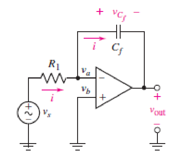
FIGURE 7.27
Expert Solution & Answer
Want to see the full answer?
Check out a sample textbook solution
Students have asked these similar questions
a) An iron ring, having a mean circumference of 250 mm and a cross-sectional area of 400
mm², is wound with a coil of 70 turns. Using the following data, calculate the current
required to set up a flux of 510µWb in the ring.
H (A/m) 350
600
1250
B (T)
1.0
1.2
1.4
b) Calculate also:
i. The inductance of the coil at the current obtained in Question 2 (a) above.
ii. The self-induced e.m.f. if this current is switched off in 0.005 s. Assume that there
is no residual flux.
A balanced three-phase, 1351-V, 60-Hz, A-connected source feeds a balanced Y-
connected load with a per-phase impedance of 360 + j150 Q as shown in Figure 1.
Calculate:
i. The readings on each of the wattmeters
ii. The power factor of the load using the wattmeter readings.
NOTE:
i.
ii.
Let VAN be the reference phasor, and the phase sequence be ABC
anticlockwise.
Assume the voltage-drop on the conductors between the source and the load
to be zero volts.
V b
V₁
W
000
000 ;
A
360 + j150
360 + j150
4
b
0000
000
B
360 + j150
C
W₂
Figure 1
a) Three 30 2 resistors are arranged as shown in Figure 1 below. They are connected to
a 480 V three-phase supply. The phase sequence is RYB anticlockwise. Calculate:
i. The total power drawn by the circuit using the phase parameters.
ii.
The power read by each wattmeter.
b) If Za, one of the 30 2 resistors, is now removed from the circuit, calculate:
R-
i.
The line currents: IR, Iv, and la
ii.
The power read by each wattmeter.
iii.
The total power drawn by the two resistors.
W₁
Be-
W2
www
'R
22
12
B
Figure 1
Chapter 7 Solutions
Loose Leaf for Engineering Circuit Analysis Format: Loose-leaf
Ch. 7.1 - Determine the current flowing through a 5 mF...Ch. 7.1 - Prob. 2PCh. 7.1 - Prob. 3PCh. 7.2 - 7.4 The current through a 200 mH inductor is shown...Ch. 7.2 - The current waveform of Fig. 7.14a has equal rise...Ch. 7.2 - Prob. 6PCh. 7.2 - Let L = 25 mH for the inductor of Fig. 7.10. (a)...Ch. 7.3 - Find Ceq for the network of Fig. 7.23. FIGURE...Ch. 7.4 - If vC(t) = 4 cos 105t V in the circuit in Fig....Ch. 7.5 - Derive an expression for vout in terms of vs for...
Ch. 7.6 - Prob. 11PCh. 7 - Making use of the passive sign convention,...Ch. 7 - Prob. 2ECh. 7 - (a) If the voltage waveform depicted in Fig. 7.42...Ch. 7 - A capacitor is constructed from two brass plates,...Ch. 7 - Prob. 5ECh. 7 - Prob. 6ECh. 7 - Design a capacitor whose capacitance can be varied...Ch. 7 - Design a capacitor whose capacitance can be varied...Ch. 7 - Prob. 9ECh. 7 - Assuming the passive sign convention, sketch the...Ch. 7 - Prob. 11ECh. 7 - Prob. 12ECh. 7 - Prob. 13ECh. 7 - Calculate the power dissipated in the 40 resistor...Ch. 7 - Prob. 15ECh. 7 - Design a 30 nH inductor using 28 AWG solid soft...Ch. 7 - Prob. 17ECh. 7 - Prob. 18ECh. 7 - Prob. 19ECh. 7 - Prob. 20ECh. 7 - Calculate vL and iL for each of the circuits...Ch. 7 - The current waveform shown in Fig. 7.14 has a rise...Ch. 7 - Determine the inductor voltage which results from...Ch. 7 - Prob. 24ECh. 7 - The voltage across a 2 H inductor is given by vL =...Ch. 7 - Calculate the energy stored in a 1 nH inductor if...Ch. 7 - Determine the amount of energy stored in a 33 mH...Ch. 7 - Making the assumption that the circuits in Fig....Ch. 7 - Calculate the voltage labeled vx in Fig. 7.52,...Ch. 7 - Prob. 30ECh. 7 - Prob. 31ECh. 7 - Determine an equivalent inductance for the network...Ch. 7 - Using as many 1 nH inductors as you like, design...Ch. 7 - Compute the equivalent capacitance Ceq as labeled...Ch. 7 - Prob. 35ECh. 7 - Prob. 36ECh. 7 - Reduce the circuit depicted in Fig. 7.59 to as few...Ch. 7 - Refer to the network shown in Fig. 7.60 and find...Ch. 7 - Prob. 39ECh. 7 - Prob. 40ECh. 7 - Prob. 41ECh. 7 - Prob. 42ECh. 7 - Prob. 43ECh. 7 - Prob. 44ECh. 7 - Prob. 45ECh. 7 - Prob. 46ECh. 7 - Prob. 47ECh. 7 - Let vs = 100e80t V with no initial energy stored...Ch. 7 - Prob. 49ECh. 7 - Prob. 50ECh. 7 - Interchange the location of R1 and Cf in the...Ch. 7 - For the integrating amplifier circuit of Fig....Ch. 7 - Prob. 53ECh. 7 - For the circuit shown in Fig. 7.73, assume no...Ch. 7 - A new piece of equipment designed to make crystals...Ch. 7 - An altitude sensor on a weather balloon provides a...Ch. 7 - One problem satellites face is exposure to...Ch. 7 - The output of a velocity sensor attached to a...Ch. 7 - A floating sensor in a certain fuel tank is...Ch. 7 - (a) If Is = 3 sin t A, draw the exact dual of the...Ch. 7 - Draw the exact dual of the simple circuit shown in...Ch. 7 - (a) Draw the exact dual of the simple circuit...Ch. 7 - (a) Draw the exact dual of the simple circuit...Ch. 7 - Prob. 64ECh. 7 - Prob. 65ECh. 7 - Prob. 66ECh. 7 - Prob. 67ECh. 7 - Prob. 68ECh. 7 - Prob. 69ECh. 7 - Prob. 70ECh. 7 - For the circuit of Fig. 7.28, (a) sketch vout over...Ch. 7 - (a) Sketch the output function vout of the...Ch. 7 - For the circuit of Fig. 7.72, (a) sketch vout over...
Knowledge Booster


Learn more about
Need a deep-dive on the concept behind this application? Look no further. Learn more about this topic, electrical-engineering and related others by exploring similar questions and additional content below.Similar questions
- A certain magnetic circuit may be regarded as consisting of three parts, A, B and C in series, each one of which has a uniform cross-sectional area. Part A has a length of 300 mm and a cross- sectional area of 450 mm². Part B has a length of 120 mm and a cross-sectional area of 300 mm². Part C is an airgap 1.0 mm in length and of cross-sectional area 350 mm². The flux in the airgap is 0.35 mWb. Neglect magnetic leakage and fringing. The magnetic characteristic for parts A and B is given by: H (A/m) 400 560 800 1280 1800 B (T) 0.7 0.85 1.0 1.15 1.25 Calculate: i. The reluctance of each part, that is, of Part A, Part B, and Part C ii. The total reluctance of the magnetic circuit. iii. The total m.m.f.arrow_forwardHW_02.pdf EE 213-01 Assignments HW_#2 Toms are as muIcate uah.instructure.com b Answered: HW_#1 HW_01.pdf EE 213-01 Assignments P Pearson MyLab and Mastering uah.instructure.com P Course Home Watc... ✓ Download → Info × Close 1) (5 pts)For the circuit shown, find the value of Ia, Ib, Ic and Va: Ib 10 Ohms + Ic 40 Ohms 20 Ohms 70 Volts a Page 1 > of 2 - ZOOM + pui via Canvas Hint: use KCL to find Ic in terms of la and lb, use KVL around the right loop to find a relationship between la and lb, use KVL around the outer loop to solve for a current value (use ohms law for the voltage drops across the resistors) 2) (5 pts) – For problem 1, show that the power supplied (delivered) by the source equals the power absorbed by the resistors. 3) (5 pts) Determine the equivalent resistance looking into terminals a-b for the two circuits shown. Use series and parallel resistor combinations. Hint: work from the opposite end of terminals a-b towards terminals a-b a) 24 Ohms 10 Ohms 8 Ohms G a REQ b)…arrow_forwardA three-phase load consists of three identical impedances connected in delta. The impedances have a value of (100 + j40) Q. The supply voltage is 440 V. The two- wattmeter method is used to determine the total power drawn by the load. One wattmeter, W₁, has its current coil connected in the blue line and its voltage coil connected between the yellow and blue lines. Calculate: a) The power measured by each wattmeter b) The power factor of the load using the wattmeter readings c) The apparent power supplied to the load d) The reactive power drawn by the load.arrow_forward
- 4- A 75 KW, 250 V shunt generator has R₁ = 0.03 2 and RF =50 2. The generator has 6 poles and is lap wound with totally 400 conductors. The generator runs at 600 rpm on full load. The bore of the machine is 42 cm (in diameter), its axial length is 28 cm and each pole subtends an angle of 54 °. Field pole a) b) c) Find the airgap flux density. (10 pt) Find the induced voltage under full load. (10 pt) Find the average number of active conductors. (5 pts) 28 cm 21 cm 60° Armaturearrow_forwarda) The phase currents in a delta - connected three-phase load are as follows: between the red and yellow lines, 60 A at p.f. 0.9 leading; between the yellow and blue lines, 40 A at 0.95 p.f lagging; between the blue and red lines, 50 A at p.f. 0.8 lagging. The supply voltage is 240 V. Draw a labeled diagram of the circuit and calculate the line currents. Note: Use VRY as the reference phasor. b) The two-wattmeter method is used to measure the total power drawn by the load in 1 (a) above. Wattmeter one has its current coil connected in the yellow line and its voltage coil connected between the yellow and red lines. Calculate: i. The power measured by each wattmeter. ii. The power factor of the load.arrow_forwardQUESTION NO. 1 a) State Lenz Law b) Explain Flux density c) A wire, 100 mm long, is moved at a uniform speed of 4 m/s at right angles to its length and to a uniform magnetic field. Calculate the density of the field if the e.m.f. generated in the wire is 0.15 V. If the wire forms part of a closed circuit having a total resistance of 0.04 2, calculate the force on the wire in newtons.arrow_forward
- In Figure (a) the drawing of the bipolar circuit was as shown in Figure 4. Draw me a unipolar circuit and how it will be in Figure (b). Please draw the circuit with the transistors.arrow_forwardSOLVE ON PAPER NOT BY CHATGPTarrow_forwardDraw fabrication layer transistor MS (schottky diode)arrow_forward
- Need Handwritten solution not using chatgt or AIarrow_forward2. Suppose G₁(s) = (s+2) G₂(s) = (s-3) C(s) Find the transfer function G(s): for each of the following three configurations R(s) shown in Figure 1. Note (a) is a cascaded (series) system, (b) is a parallel system, and (c) is a feedback (closed-loop) system. € (c) C(s) R(s) G₁(s) G2(5) G₁(s) R(s) C(s) G2(s) C(s) R(s) G₁(s) G₂(s) Figure 1arrow_forwardDetermine the transformer's active power losses and primary voltage (Figure 1). The busbar's voltage at the transformer's secondary side is 20.5 kV. Load P is 6 MW, and the power factor is 0.95ind.arrow_forward
arrow_back_ios
SEE MORE QUESTIONS
arrow_forward_ios
Recommended textbooks for you
 Introductory Circuit Analysis (13th Edition)Electrical EngineeringISBN:9780133923605Author:Robert L. BoylestadPublisher:PEARSON
 Delmar's Standard Textbook Of ElectricityElectrical EngineeringISBN:9781337900348Author:Stephen L. HermanPublisher:Cengage Learning
 Programmable Logic ControllersElectrical EngineeringISBN:9780073373843Author:Frank D. PetruzellaPublisher:McGraw-Hill Education
 Fundamentals of Electric CircuitsElectrical EngineeringISBN:9780078028229Author:Charles K Alexander, Matthew SadikuPublisher:McGraw-Hill Education
 Electric Circuits. (11th Edition)Electrical EngineeringISBN:9780134746968Author:James W. Nilsson, Susan RiedelPublisher:PEARSON
 Engineering ElectromagneticsElectrical EngineeringISBN:9780078028151Author:Hayt, William H. (william Hart), Jr, BUCK, John A.Publisher:Mcgraw-hill Education,
Introductory Circuit Analysis (13th Edition)
Electrical Engineering
ISBN:9780133923605
Author:Robert L. Boylestad
Publisher:PEARSON
Delmar's Standard Textbook Of Electricity
Electrical Engineering
ISBN:9781337900348
Author:Stephen L. Herman
Publisher:Cengage Learning
Programmable Logic Controllers
Electrical Engineering
ISBN:9780073373843
Author:Frank D. Petruzella
Publisher:McGraw-Hill Education
Fundamentals of Electric Circuits
Electrical Engineering
ISBN:9780078028229
Author:Charles K Alexander, Matthew Sadiku
Publisher:McGraw-Hill Education
Electric Circuits. (11th Edition)
Electrical Engineering
ISBN:9780134746968
Author:James W. Nilsson, Susan Riedel
Publisher:PEARSON
Engineering Electromagnetics
Electrical Engineering
ISBN:9780078028151
Author:Hayt, William H. (william Hart), Jr, BUCK, John A.
Publisher:Mcgraw-hill Education,
ENA 9.2(1)(En)(Alex) Sinusoids & Phasors - Explanation with Example 9.1 ,9.2 & PP 9.2; Author: Electrical Engineering Academy;https://www.youtube.com/watch?v=vX_LLNl-ZpU;License: Standard YouTube License, CC-BY
Electrical Engineering: Ch 10 Alternating Voltages & Phasors (8 of 82) What is a Phasor?; Author: Michel van Biezen;https://www.youtube.com/watch?v=2I1tF3ixNg0;License: Standard Youtube License