
Concept explainers
Videos
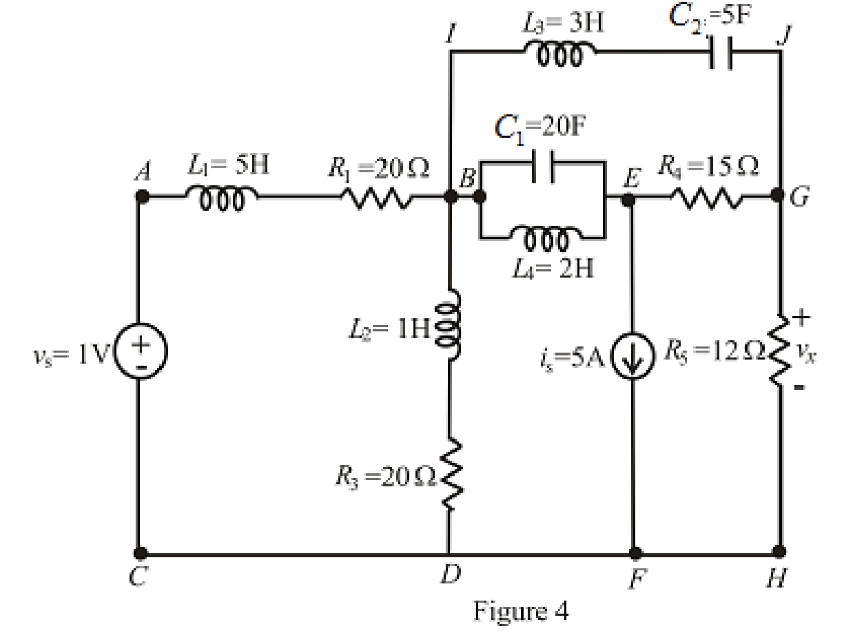
Calculate the voltage labeled vx in Fig. 7.52, assuming the circuit has been running a very long time, if (a) a 10 Ω resistor is connected between terminals x and y; (b) a 1 H inductor is connected between terminals x and y; (c) a 1 F capacitor is connected between terminals x and y; (d) a 4 H inductor in parallel with a 1 Ω resistor is connected between terminals x and y.
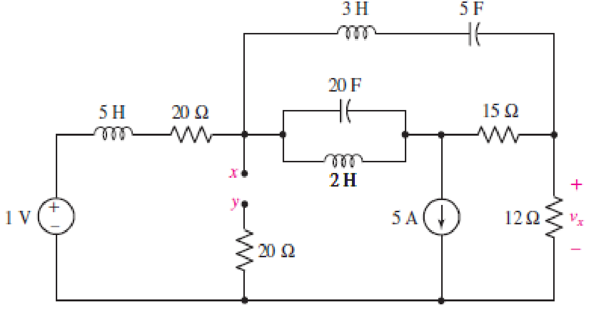
FIGURE 7.52
(a)
Find the voltage
Answer to Problem 29E
The voltage
Explanation of Solution
Given data:
Value of resistance connected between terminals
Calculation:
The redrawn circuit is shown in Figure 1 as follows:
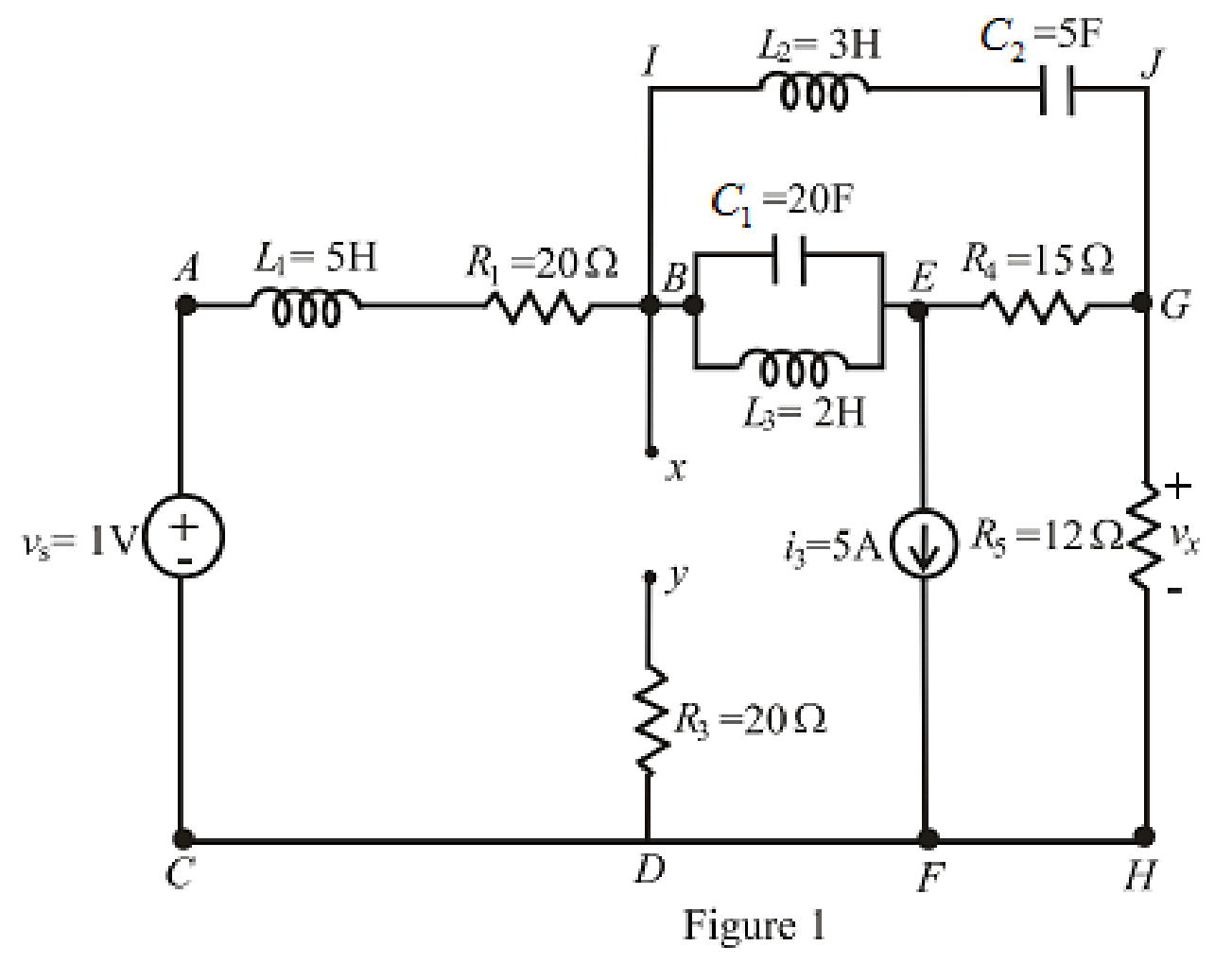
Here,
The redrawn circuit is shown in Figure 2.
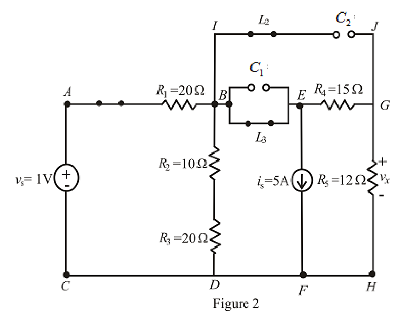
Refer to the Figure 2:
When steady state is reached, all the inductors connected are short circuited and all the capacitors connected are open circuited.
The equivalent resistance for series combination across branch is as follows:
Substitute
The redrawn circuit is shown in Figure 3 as follows:
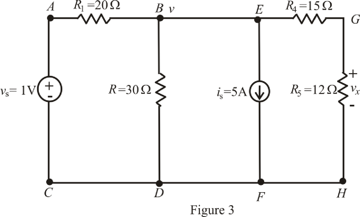
Refer to the redrawn Figure 3:
The expression for the nodal analysis at node voltage
Here,
The expression for the current across the resistance
The expression for the voltage across the resistance
The current across the resistances
Substitute
Solve for
Substitute
Substitute
Conclusion:
Thus, the voltage
(b)
Find the voltage
Answer to Problem 29E
The voltage
Explanation of Solution
Given Data:
Value of inductor connected between terminals
Calculation:
The redrawn circuit with inductor connected across branch
The redrawn circuit is shown in Figure 4 as follows:
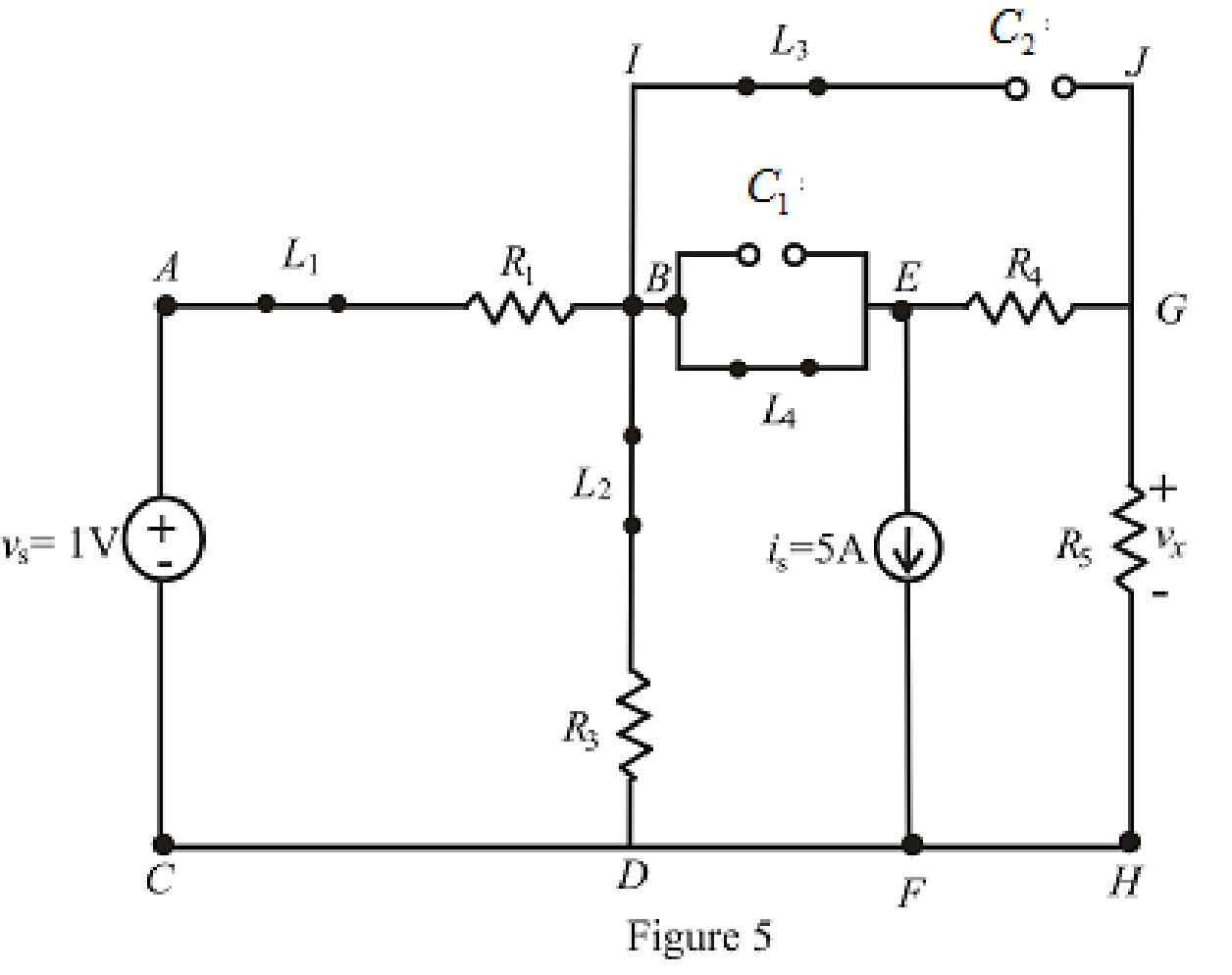
Refer to the Figure 5:
When steady state is reached, the inductor connected across branch
The redrawn circuit is shown in Figure 6 as follows:
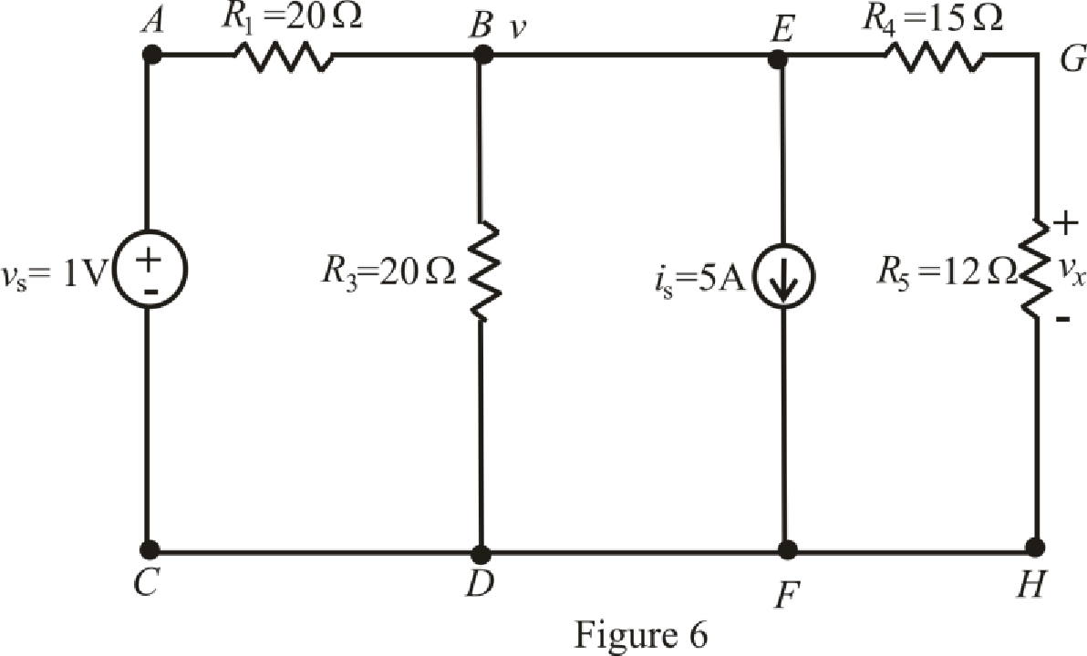
The expression for the nodal analysis at node voltage
The expression for the current across the resistance
The expression for the current across the resistance
The current across the resistances
Substitute
Solve for
Substitute
Substitute
Conclusion:
Thus, the voltage
(c)
Find the voltage
Answer to Problem 29E
The voltage
Explanation of Solution
Given data:
Value of capacitor connected between terminals
Calculation:
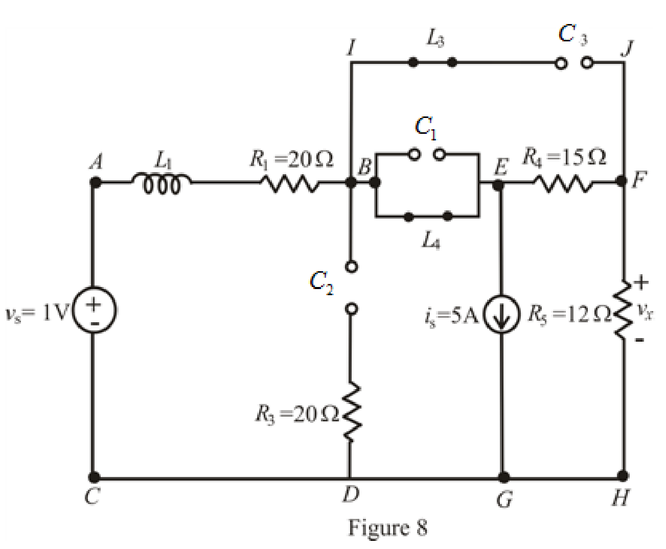
The redrawn circuit of capacitor connected across branch
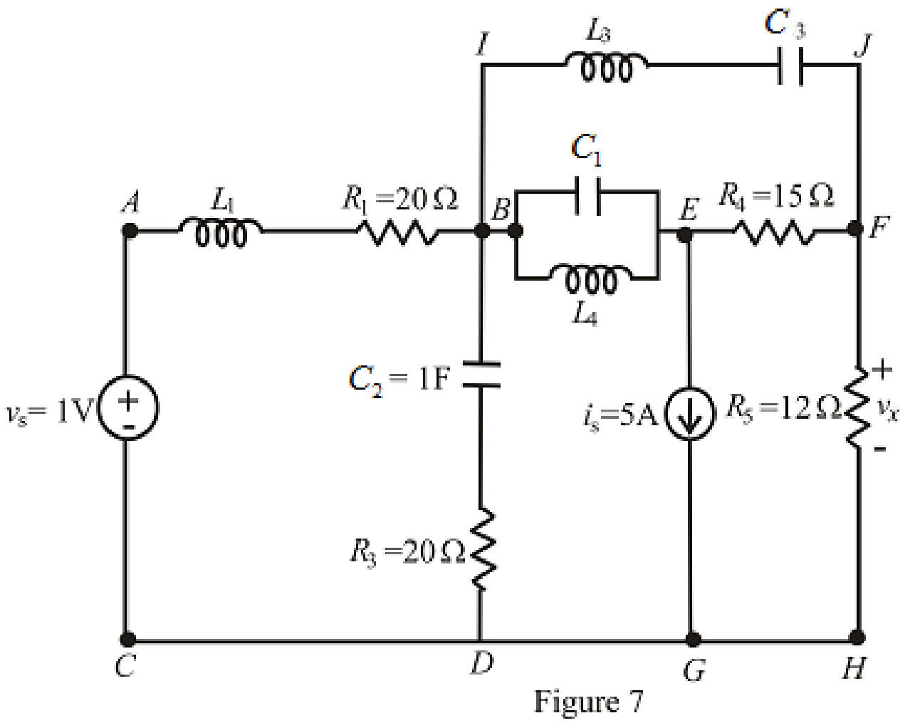
Refer to the redrawn Figure 7:
The redrawn circuit is shown in Figure 8 as follows:
When steady state is reached, thecapacitors connected across branch
The redrawn circuit is shown in Figure 9 as follows:
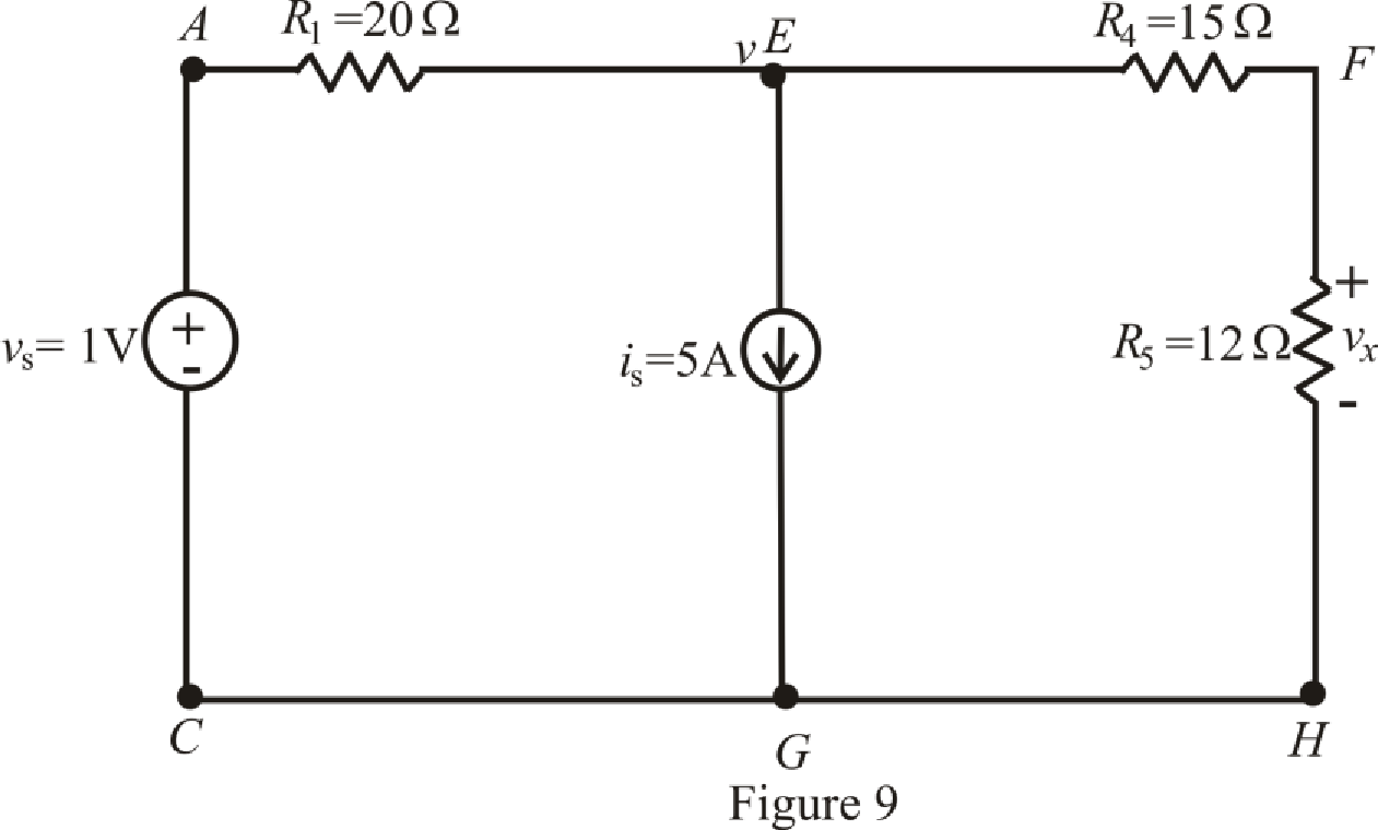
Refer to the Figure 9:
The expression for the nodal analysis at node voltage
The expression for the current across the resistance
The expression for the voltage across the resistance
The current across the resistances
Substitute
Solve for
Substitute
Substitute
Conclusion:
Thus, the voltage
(d)
Find the voltage
Answer to Problem 29E
The voltage
Explanation of Solution
Given Data:
Value of inductor connected between terminal
Value of resistor connected in parallel with inductor across terminal
Calculation:
The redrawn circuit is shown in Figure 10:
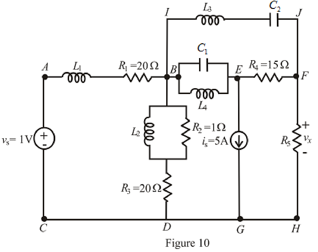
Refer to the redrawn Figure 10:
The redrawn circuit is shown in Figure 11 as follows:
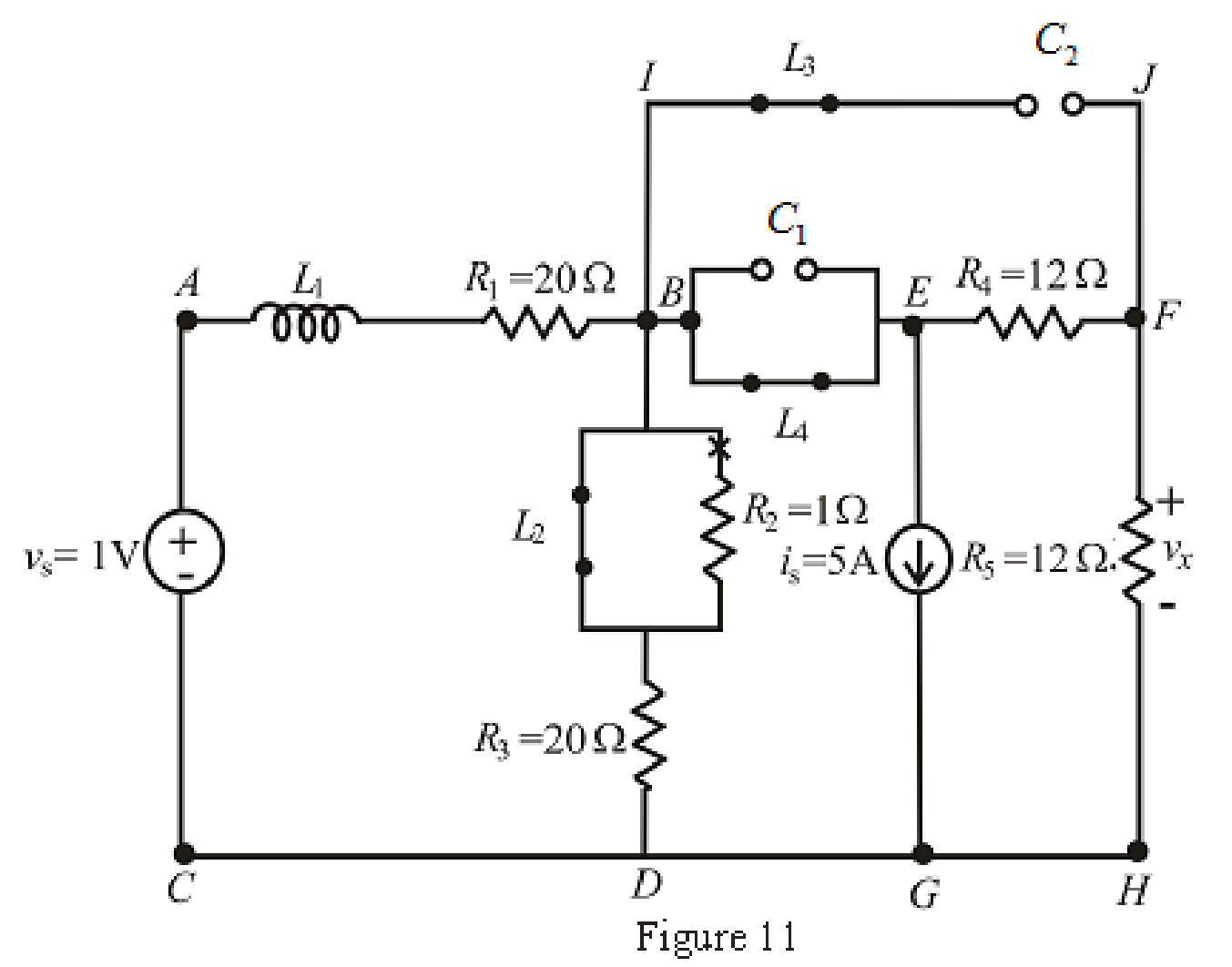
When steady state is reached, the inductor connected across branch
The redrawn circuit is shown in Figure 12,
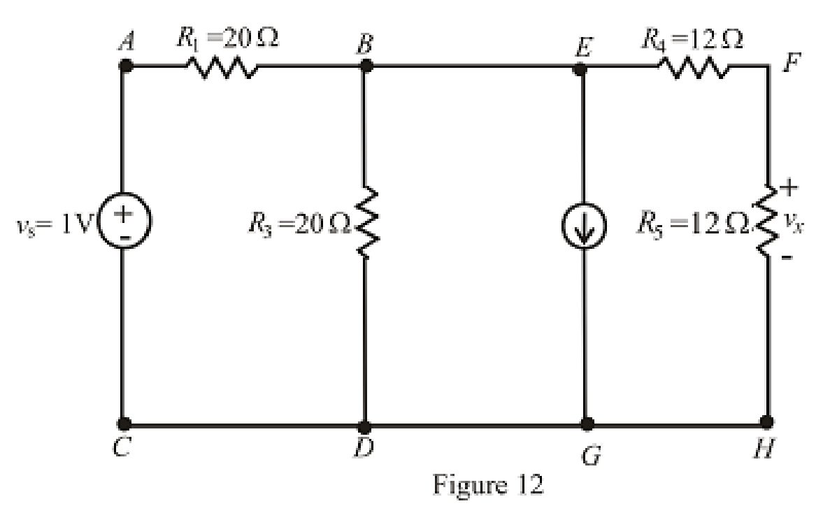
Refer to the Figure 12:
The expression for the nodal analysis at node voltage
The expression for the current across the resistance
The expression for the voltage across the resistance
The current across the resistances
Substitute
Solve for
Substitute
Substitute
Conclusion:
Thus, the voltage
Want to see more full solutions like this?
Chapter 7 Solutions
Loose Leaf for Engineering Circuit Analysis Format: Loose-leaf


- the question with its answer but i still dont see how the expansion and the calculation done. please show detailed steps.arrow_forwardQ6) Find the current density J for the magnetic field intensity vectors: (a) H = x²yax + y²zay - 2xzaz pzap + p³a + 3pz²a (b) H = sin cos (c) H = a,arrow_forwardConsider the following circuit which implements functions fand g: x1 x3 x1 x3 D X4 x1 x2 x2 m الله الله X4 x2 X4 x3 x1 x4 x1 D g a) What is the cost of this circuit, assuming that the input variables are available in both true and complemented forms? b) Redesign the circuit to implement the same functions, but at as low a cost as possible. What is the cost of your circuit?arrow_forward
- Q2) Line x = 0, y = 0,0arrow_forwardConsider the following logic functions: f = x₁x2x3 + x2X4 +X1X2X4 +X2X3X+X1X2X3 8 = (x2+x3 + x4)(x1+x2 + x4)(x2+x3+X4)(x1+x2+x3)(x1+x2+x4) Prove or disprove that f = garrow_forwardNo AI, Use pencil and paperarrow_forward1. For the circuit shown, let Is = 10, R₁-45, R2-5, R3-5, and R4-45, to find: (choose the closest value in volts) (V) {NOTE: On Multiple Choice Questions, like this problem, you have only one attempt } • Vab 50 (V) -25 225 R₁ a R2 RA b R3 Vabarrow_forwardpower systemsarrow_forwardFind G(s) = Vs(s) / Ve(s) for this circuit belowarrow_forwardCalculate the magnitude of the current in the coils e1, e2 of the magnetic circuit, if: ɸa = 3,00 x 10⁻³ Wb, φb = 0,80 x 10⁻³ Wb, ɸc = 2,20 x 10⁻³ Wb L AB = 0,10 m, L AFEB = L ACDB = 0,40 m AAB = 5,0 cm2 A AFEB = A ACDB = 20 cm2 Material characteristics H (At/m) 240 350 530 1300 5000 9000 B (T) 0,7 0,9 1,1 1,3 1,5 1,6arrow_forwardPower systemsarrow_forwardExplain the advantages and disadvantages of using silicon (Si) anode versus graphitic anode (C6) and write charging reactions for these anodes. Explain the effect of increasing state of charge window (SOC) of lithium battery and how SOC-window impact energy density and cycle life of the battery.arrow_forwardarrow_back_iosSEE MORE QUESTIONSarrow_forward_ios
 Introductory Circuit Analysis (13th Edition)Electrical EngineeringISBN:9780133923605Author:Robert L. BoylestadPublisher:PEARSON
 Delmar's Standard Textbook Of ElectricityElectrical EngineeringISBN:9781337900348Author:Stephen L. HermanPublisher:Cengage Learning
 Programmable Logic ControllersElectrical EngineeringISBN:9780073373843Author:Frank D. PetruzellaPublisher:McGraw-Hill Education
 Fundamentals of Electric CircuitsElectrical EngineeringISBN:9780078028229Author:Charles K Alexander, Matthew SadikuPublisher:McGraw-Hill Education
 Electric Circuits. (11th Edition)Electrical EngineeringISBN:9780134746968Author:James W. Nilsson, Susan RiedelPublisher:PEARSON
 Engineering ElectromagneticsElectrical EngineeringISBN:9780078028151Author:Hayt, William H. (william Hart), Jr, BUCK, John A.Publisher:Mcgraw-hill Education,