
Loose Leaf for Engineering Circuit Analysis Format: Loose-leaf
9th Edition
ISBN: 9781259989452
Author: Hayt
Publisher: Mcgraw Hill Publishers
expand_more
expand_more
format_list_bulleted
Videos
Textbook Question
Chapter 7, Problem 34E
Compute the equivalent capacitance Ceq as labeled in Fig. 7.56.
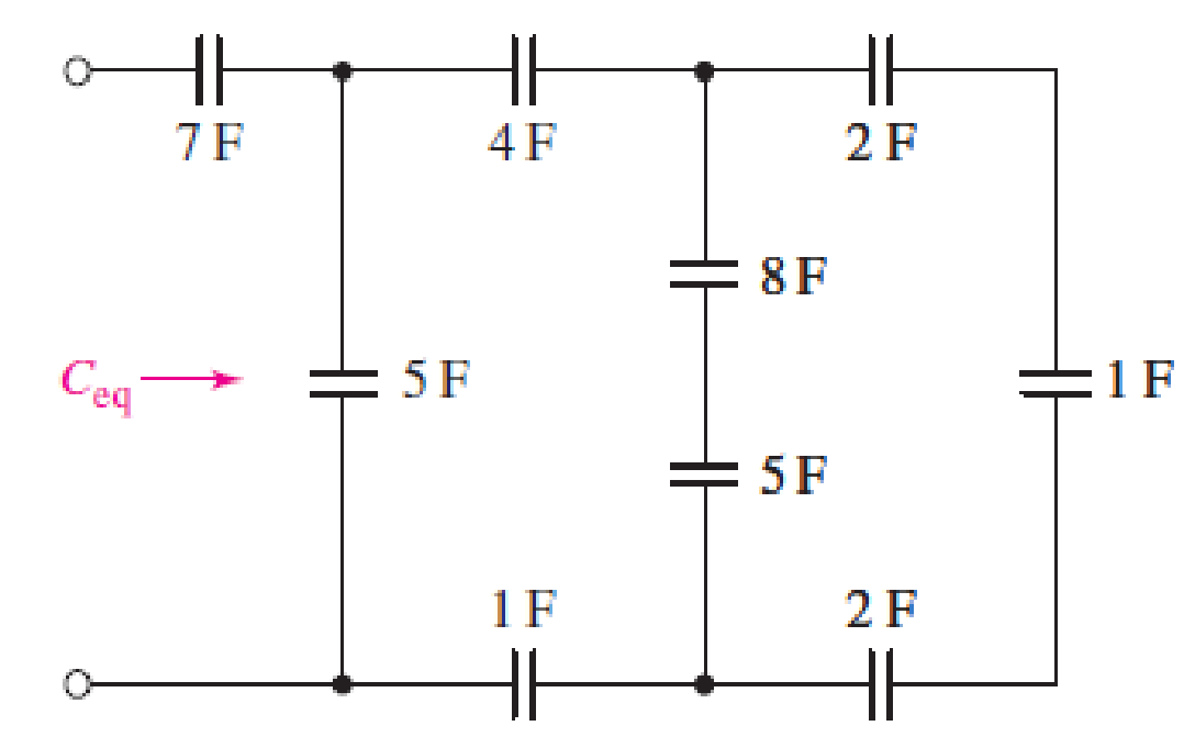
FIGURE 7.56
Expert Solution & Answer
Want to see the full answer?
Check out a sample textbook solution
Students have asked these similar questions
Find Vfinal when Vs
up
and Vs V. Which LED will light
in each case? Red or Green? Justify your answers. Fill the
table below.
Vs
8 ΚΩ
Vos
Χρι
+
3 ΚΩ
www
6 ΚΩ
ww
4 ΚΩ Yo
www
Vo
Vec-12 V
Nol
V final
Vm
w
3 ΚΩ
5 V
38 ΚΩ
R= 1 kQ
V
-12 V
Red LED
Green
LED
Vs
Vo
Vfinal
Which LED is ON?
V
Circuits help please solve and explain. Question in images provided
+
V 6.2 A
1.2 A
S
R
4 Ω
Find the source voltage Vs
0.8 A
Chapter 7 Solutions
Loose Leaf for Engineering Circuit Analysis Format: Loose-leaf
Ch. 7.1 - Determine the current flowing through a 5 mF...Ch. 7.1 - Prob. 2PCh. 7.1 - Prob. 3PCh. 7.2 - 7.4 The current through a 200 mH inductor is shown...Ch. 7.2 - The current waveform of Fig. 7.14a has equal rise...Ch. 7.2 - Prob. 6PCh. 7.2 - Let L = 25 mH for the inductor of Fig. 7.10. (a)...Ch. 7.3 - Find Ceq for the network of Fig. 7.23. FIGURE...Ch. 7.4 - If vC(t) = 4 cos 105t V in the circuit in Fig....Ch. 7.5 - Derive an expression for vout in terms of vs for...
Ch. 7.6 - Prob. 11PCh. 7 - Making use of the passive sign convention,...Ch. 7 - Prob. 2ECh. 7 - (a) If the voltage waveform depicted in Fig. 7.42...Ch. 7 - A capacitor is constructed from two brass plates,...Ch. 7 - Prob. 5ECh. 7 - Prob. 6ECh. 7 - Design a capacitor whose capacitance can be varied...Ch. 7 - Design a capacitor whose capacitance can be varied...Ch. 7 - Prob. 9ECh. 7 - Assuming the passive sign convention, sketch the...Ch. 7 - Prob. 11ECh. 7 - Prob. 12ECh. 7 - Prob. 13ECh. 7 - Calculate the power dissipated in the 40 resistor...Ch. 7 - Prob. 15ECh. 7 - Design a 30 nH inductor using 28 AWG solid soft...Ch. 7 - Prob. 17ECh. 7 - Prob. 18ECh. 7 - Prob. 19ECh. 7 - Prob. 20ECh. 7 - Calculate vL and iL for each of the circuits...Ch. 7 - The current waveform shown in Fig. 7.14 has a rise...Ch. 7 - Determine the inductor voltage which results from...Ch. 7 - Prob. 24ECh. 7 - The voltage across a 2 H inductor is given by vL =...Ch. 7 - Calculate the energy stored in a 1 nH inductor if...Ch. 7 - Determine the amount of energy stored in a 33 mH...Ch. 7 - Making the assumption that the circuits in Fig....Ch. 7 - Calculate the voltage labeled vx in Fig. 7.52,...Ch. 7 - Prob. 30ECh. 7 - Prob. 31ECh. 7 - Determine an equivalent inductance for the network...Ch. 7 - Using as many 1 nH inductors as you like, design...Ch. 7 - Compute the equivalent capacitance Ceq as labeled...Ch. 7 - Prob. 35ECh. 7 - Prob. 36ECh. 7 - Reduce the circuit depicted in Fig. 7.59 to as few...Ch. 7 - Refer to the network shown in Fig. 7.60 and find...Ch. 7 - Prob. 39ECh. 7 - Prob. 40ECh. 7 - Prob. 41ECh. 7 - Prob. 42ECh. 7 - Prob. 43ECh. 7 - Prob. 44ECh. 7 - Prob. 45ECh. 7 - Prob. 46ECh. 7 - Prob. 47ECh. 7 - Let vs = 100e80t V with no initial energy stored...Ch. 7 - Prob. 49ECh. 7 - Prob. 50ECh. 7 - Interchange the location of R1 and Cf in the...Ch. 7 - For the integrating amplifier circuit of Fig....Ch. 7 - Prob. 53ECh. 7 - For the circuit shown in Fig. 7.73, assume no...Ch. 7 - A new piece of equipment designed to make crystals...Ch. 7 - An altitude sensor on a weather balloon provides a...Ch. 7 - One problem satellites face is exposure to...Ch. 7 - The output of a velocity sensor attached to a...Ch. 7 - A floating sensor in a certain fuel tank is...Ch. 7 - (a) If Is = 3 sin t A, draw the exact dual of the...Ch. 7 - Draw the exact dual of the simple circuit shown in...Ch. 7 - (a) Draw the exact dual of the simple circuit...Ch. 7 - (a) Draw the exact dual of the simple circuit...Ch. 7 - Prob. 64ECh. 7 - Prob. 65ECh. 7 - Prob. 66ECh. 7 - Prob. 67ECh. 7 - Prob. 68ECh. 7 - Prob. 69ECh. 7 - Prob. 70ECh. 7 - For the circuit of Fig. 7.28, (a) sketch vout over...Ch. 7 - (a) Sketch the output function vout of the...Ch. 7 - For the circuit of Fig. 7.72, (a) sketch vout over...
Knowledge Booster


Learn more about
Need a deep-dive on the concept behind this application? Look no further. Learn more about this topic, electrical-engineering and related others by exploring similar questions and additional content below.Similar questions
- Determine i(t) for t≥ 0 given that the circuit below had been in steady state for a long time prior to t = 0. Also, I₁ = 1 5 A, R₁ =22, R2 =10 Q2, R3 = 32, R4 =7 2, and L=0.15 H. Also fill the table. m L ww R2 t = 0 R₁ 29 R3 R4 Time 0 iL(t) 0 8arrow_forwardPlease help explain this problemarrow_forward+ P = 16 W w w P = 8 W I R₁ R2 E = RT=322 1- Determine R1, R2, E ΙΩarrow_forward
- + 30 V = - 20 V + R 2- Use KVL to find the voltage V - V + + 8 Varrow_forwardFind the Thévenin equivalent circuit for the portions of the networks in Figure external to the elements between points a and b. a R₁ 2002 I = 0.1 A 0° Xc : 32 Ω R2 = 6802 20 Ω фъarrow_forwardFind the Norton equivalent circuit for the network external to the elements between a and b for the networks in Figure. E1 = 120 V Z 0° R ww 10 Ω Xc XL · 000 802 802 ① I = 0.5 AZ 60° ZL barrow_forward
- Using superposition, determine the current through inductance XL for each network in Figure I = 0.3 A 60° XL 000 802 XC 502 Ω E 10 V0° =arrow_forwardFind the Thévenin equivalent circuit for the portions of the networks in Figure external to the elements between points a and b. E = 20 VZ0° + R ww 2 ΚΩ Хо XL 000 6ΚΩ 3 ΚΩ b RLarrow_forwardWhat percentage of the full-load current of a thermally protected continuous-duty motor of more than one Hp can the trip current be, if the full-load current is 15 amperes? Ο 122 Ο 140 156 O 170arrow_forward
- Q3arrow_forwardIn thinkercad can you make a parallel series circuit with a resistors and a voltage source explain how the voltage and current moves through the circuit, and explaining all the components, and if you were to break the circuit to find the current how would you do that? Please show visuals if possible.arrow_forwardIn thinkercad can you make a series circuit with a resistors and a voltage source explain how the voltage and current moves through the circuit, and explaining all the components, and if you were to break the circuit to find the current how would you do that? Please show visuals if possible.arrow_forward
arrow_back_ios
SEE MORE QUESTIONS
arrow_forward_ios
Recommended textbooks for you
 Introductory Circuit Analysis (13th Edition)Electrical EngineeringISBN:9780133923605Author:Robert L. BoylestadPublisher:PEARSON
 Delmar's Standard Textbook Of ElectricityElectrical EngineeringISBN:9781337900348Author:Stephen L. HermanPublisher:Cengage Learning
 Programmable Logic ControllersElectrical EngineeringISBN:9780073373843Author:Frank D. PetruzellaPublisher:McGraw-Hill Education
 Fundamentals of Electric CircuitsElectrical EngineeringISBN:9780078028229Author:Charles K Alexander, Matthew SadikuPublisher:McGraw-Hill Education
 Electric Circuits. (11th Edition)Electrical EngineeringISBN:9780134746968Author:James W. Nilsson, Susan RiedelPublisher:PEARSON
 Engineering ElectromagneticsElectrical EngineeringISBN:9780078028151Author:Hayt, William H. (william Hart), Jr, BUCK, John A.Publisher:Mcgraw-hill Education,
Introductory Circuit Analysis (13th Edition)
Electrical Engineering
ISBN:9780133923605
Author:Robert L. Boylestad
Publisher:PEARSON
Delmar's Standard Textbook Of Electricity
Electrical Engineering
ISBN:9781337900348
Author:Stephen L. Herman
Publisher:Cengage Learning
Programmable Logic Controllers
Electrical Engineering
ISBN:9780073373843
Author:Frank D. Petruzella
Publisher:McGraw-Hill Education
Fundamentals of Electric Circuits
Electrical Engineering
ISBN:9780078028229
Author:Charles K Alexander, Matthew Sadiku
Publisher:McGraw-Hill Education
Electric Circuits. (11th Edition)
Electrical Engineering
ISBN:9780134746968
Author:James W. Nilsson, Susan Riedel
Publisher:PEARSON
Engineering Electromagnetics
Electrical Engineering
ISBN:9780078028151
Author:Hayt, William H. (william Hart), Jr, BUCK, John A.
Publisher:Mcgraw-hill Education,
Inductors Explained - The basics how inductors work working principle; Author: The Engineering Mindset;https://www.youtube.com/watch?v=KSylo01n5FY;License: Standard Youtube License