
Laboratory Manual for Introductory Circuit Analysis
13th Edition
ISBN: 9780133923780
Author: Robert L. Boylestad, Gabriel Kousourou
Publisher: PEARSON
expand_more
expand_more
format_list_bulleted
Concept explainers
Videos
Textbook Question
Chapter 7, Problem 23P
For the network of Fig. 7.86:
a. Find the voltages
b. Calculate the current
c. Determine the voltage
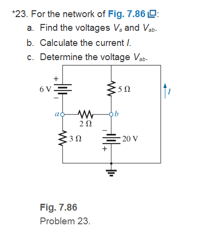
Fig. 7.86
Expert Solution & Answer
Want to see the full answer?
Check out a sample textbook solution
Students have asked these similar questions
Don't use ai to answer I will report you answer
A three-phase transmission line supplies power to three loads at a voltage
408 Vrms (line to line). The loads are as follows:
Load 1:
S₁ = 100+ j50 VA
Load 2:
S₂ = 40-j20 VA
Load 3:
S3 = 10 + j0 VA
Find the magnitude of the line current | Line and the combined power factor of
the loads.
Hint:
Steral \= √3 | Vime |× | Ime |
line
line
Can you show why the answer to this question R = 199 ohm?
Chapter 7 Solutions
Laboratory Manual for Introductory Circuit Analysis
Ch. 7 - Which elements (individual elements, not...Ch. 7 - Repeat Problem 1 for the networks of Fig. 7.65....Ch. 7 - Determine RT for the networks in Fig. 7.66. Fig....Ch. 7 - Determine RT for the networks in Fig. 7.67. Fig....Ch. 7 - Find the total resistance for the configuration of...Ch. 7 - The total resistance RT for the network of Fig....Ch. 7 - For the network in Fig. 7.70. a. Does...Ch. 7 - For the network in Fig. 7.71: a. Determine RT. b....Ch. 7 - For the network of Fig. 7.72: a. find the currents...Ch. 7 - For the network of Fig. 7.73: Find the voltages V3...
Ch. 7 - For the network of Fig. 7.74 a. Find the voltages...Ch. 7 - For the circuit board in Fig. 7.75: Find the total...Ch. 7 - Find the value of each resistor for the network of...Ch. 7 - Find the resistance RT for the network of Fig....Ch. 7 - For the network in Fig. 7.78: a. Find currents...Ch. 7 - a. Find the magnitude and direction of the...Ch. 7 - Determine the currents I1andI2 for the network in...Ch. 7 - For the network in Fig. 7.81: a. Determine the...Ch. 7 - For the network in Fig. 7.82: a. Determine the...Ch. 7 - Determine the dc levels for the transistor network...Ch. 7 - For the network in Fig. 7.84: Determine the...Ch. 7 - For the network in Fig. 7.852 Determine RT by...Ch. 7 - For the network of Fig. 7.86: a. Find the voltages...Ch. 7 - For the network in Fig. 7.87: a. Determine the...Ch. 7 - For the network in Fig. 7.88 find the resistance...Ch. 7 - If all the resistors of the cube in Fig. 7.89 are...Ch. 7 - For the ladder network in Fig. 7.90: a. Find the...Ch. 7 - For the ladder network in Fig. 7.91: a. Determine...Ch. 7 - Given the voltage divider supply in Fig. 7.92: a....Ch. 7 - Determine the voltage divider supply resistors for...Ch. 7 - A studio lamp requires 40 V at 50 mA to burn...Ch. 7 - For the system in Fig. 7.94 a. At first exposure,...Ch. 7 - For the potentiometer in Fig. 7.95: a. What are...Ch. 7 - Prob. 34PCh. 7 - Given the voltmeter reading V = 27 V in Fig. 7.97...Ch. 7 - Determine the power delivered to the 6 load in...Ch. 7 - For the multiple ladder configuration in Fig....Ch. 7 - An iron-vane movement is rated 1 mA, 100 . a. What...Ch. 7 - Using a 50 A, 1000 movement, design a multirange...Ch. 7 - An iron-vane movement is rated 50 A , 1000 a....Ch. 7 - Using a 1 mA, 1000 movement, design a multirange...Ch. 7 - A digital meter has an internal resistance of 10 M...Ch. 7 - a. Design a series ohmmeter using a 100 A, 1000...Ch. 7 - Prob. 44PCh. 7 - Determine the reading of the ohmmeter for each...Ch. 7 - Using PSpice or Multisim, verify the result of...Ch. 7 - Using PSpice or Multisim, Confirm the solutions of...Ch. 7 - Using PSpice or Multisim, verify the result of...Ch. 7 - Using PSpice or Multisim, find voltage V6 of Fig....Ch. 7 - Using PSpice or Multisim, find voltages Vb and Vc...
Additional Engineering Textbook Solutions
Find more solutions based on key concepts
How does a computers main memory differ from its auxiliary memory?
Java: An Introduction to Problem Solving and Programming (8th Edition)
CONCEPT QUESTIONS
15.CQ3 The ball rolls without slipping on the fixed surface as shown. What is the direction ...
Vector Mechanics for Engineers: Statics and Dynamics
The solid steel shaft AC has a diameter of 25 mm and is supported by smooth bearings at D and E. It is coupled ...
Mechanics of Materials (10th Edition)
Porter’s competitive forces model: The model is used to provide a general view about the firms, the competitors...
Management Information Systems: Managing The Digital Firm (16th Edition)
This optional Google account security feature sends you a message with a code that you must enter, in addition ...
SURVEY OF OPERATING SYSTEMS
1.2 Explain the difference between geodetic and plane
surveys,
Elementary Surveying: An Introduction To Geomatics (15th Edition)
Knowledge Booster


Learn more about
Need a deep-dive on the concept behind this application? Look no further. Learn more about this topic, electrical-engineering and related others by exploring similar questions and additional content below.Similar questions
- 2.5. Find the half-power beamwidth (HPBW) and first-null beamwidth (FNBW), in radians and degrees, for the following normalized radiation intensities: (a) U(9) cos θ cos(20) (b) U(θ)-cos2 θ cos2(26) (c) U(θ) = cos(θ) cos(30) (0 < θ < 900,0 < φ 360) (d) U(t) = cos2(9) cos2(39) (e) U(9) = cos(29) cos(39) (f) U (ecos (20) cos (30)arrow_forwardDon't use ai to answer I will report you answerarrow_forwardDon't use ai to answer I will report you answerarrow_forward
- A 60 Hz, 230 kV, 275 km long, uncompensated three-phase transmission line consists of three conductors bundled by phase, such that each conductor in the line is of the ACSR Falcon type. The separation between each bundled conductor is d = 45 cm and the separation between each phase of the line is 2.4 m. Calculate: "The parameters R, L, C of the line in Q2/km; µH/m and nF/m. And the total values of ZL and YC in Q and S, respectively, and in polar coordinates." Generalized constants A, B, C and D of the line, according to the type of transmission line. Present the results in rectangular coordinates. If a three-phase wye load draws 3/4 of the nominal current of the 300 MW system with FP = 0.85 lagging and at 230 kV, calculate: (a) Current at the load in KA (b) Voltage at the source in KV, (c) Current at the source in kA and (d) power at the source in MVA. Obtain the results per phase. Transmission line voltage regulation percentagearrow_forwardDetermine the required EMT size for the following combination of conductors:18. Four 8 AWG Type THW and four 12 AWG Type THW:19. Three 350 kcmil and one 250 kcmil Type XHHW conductors and a 4 AWG bare conductor:20. In a nonmetallic-sheathed (Type NM) cable installation, a 10⁄3 with equipmentgrounding conductor is installed in a metal octagonal box to supply two 12⁄2 withequipment grounding conductor branch-circuit cables. What is the minimum sizebox? The box contains internal cable clampsarrow_forwardFor problems 8 and 9, determine the correct box size for each of the following conditions:8. Two nonmetallic sheathed cables with two 12 AWG conductors, an equipment groundingconductor, and a switch in a metal box without a plaster ring.9. A raceway run serving a series of luminaires, connected to a total of three circuits. Theluminaires are supplied by 120 volts from a 3-phase, 4-wire system. Each box will containtwo circuits running through the box and a third circuit connected to a luminaire, which issupported by a luminaire stud in the box. Use 12 AWG Type THHN conductors.arrow_forward
- 28. The minimum size raceway for the following conductors is: a. Three, 250 kcmil conductors with XHHW insulation b. One, 3⁄0 AWG conductor with XHHW insulation c. One, 4 AWG conductor with XHHW insulation29. The minimum size raceway for the following conductors is: a. Twelve, 6 AWG conductors with THHN insulation b. Nine, 8 AWG conductors with THHN insulation c. Eighteen, 10 AWG conductor with THHN insulation d. One, 10 AWG equipment grounding conductor with THHN insulation30. The minimum size wireway for the following with parallel conductors is: a. Two sets of three, 250 kcmil conductors with XHHW insulation b. Two, 3⁄0 AWG conductors with XHHW insulation c. 1, 4 AWG conductor with XHHW insulation d. The conductors terminate on three power distribution blocks. Each one has adimension of 4 in. wide and 3 in. high:arrow_forwardbox fill calculationsarrow_forwardTwo trade size 3 raceways enter a pull box directly across from each other. No other raceways enter the box. What are the minimum dimensions of the box?11. Length ______________________12. Width ______________________13. Depth ______________________Two trade size 3 raceways enter a pull box at right angles to each other. No other racewaysenter the box. What are the minimum dimensions of the box?14. Length ______________________15. Width ______________________16. Depth ______________________arrow_forward
- not use ai pleasearrow_forwardFor Questions 21, 22, and 23, two 3-in. raceways enter a pull box, one through a side and theother in the back. Four 500 kcmil, type THHN conductors will be installed in the raceway.No other raceways enter the box. What are the minimum dimensions of the pull box 21. Length ________________22. Width ________________23. Depth ________________arrow_forwardFor Questions 24, 25, 26, and 27, determine the answers using the information shown in the drawing. Trade size 2 conduit Trade size 2 conduit Trade size 3 conduit Trade size 3 conduit Trade size 2 conduit Trade size 2 conduit 24. Dimension a must be at least. 25. Dimension b must be at least the same conductors). inches. inches (the raceways contain inches. 26. Dimension c must be at least 27. Do you foresee any difficulties in installing the conductors in these raceways? Explain.arrow_forward
arrow_back_ios
SEE MORE QUESTIONS
arrow_forward_ios
Recommended textbooks for you
 Delmar's Standard Textbook Of ElectricityElectrical EngineeringISBN:9781337900348Author:Stephen L. HermanPublisher:Cengage Learning
Delmar's Standard Textbook Of Electricity
Electrical Engineering
ISBN:9781337900348
Author:Stephen L. Herman
Publisher:Cengage Learning
Current Divider Rule; Author: Neso Academy;https://www.youtube.com/watch?v=hRU1mKWUehY;License: Standard YouTube License, CC-BY