
Laboratory Manual for Introductory Circuit Analysis
13th Edition
ISBN: 9780133923780
Author: Robert L. Boylestad, Gabriel Kousourou
Publisher: PEARSON
expand_more
expand_more
format_list_bulleted
Concept explainers
Videos
Textbook Question
Chapter 7, Problem 45P
Determine the reading of the ohmmeter for each configuration of Fig. 7.100.
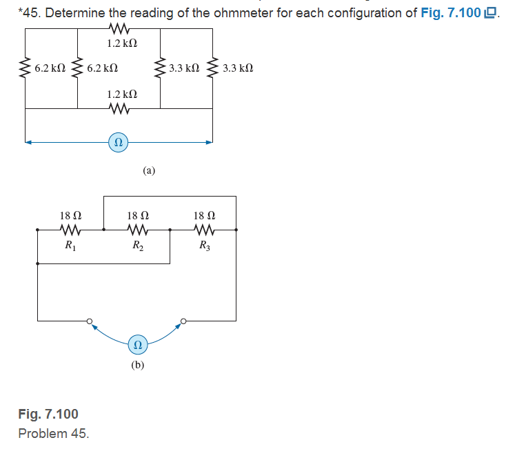
Fig. 7.100
Expert Solution & Answer
Want to see the full answer?
Check out a sample textbook solution
Students have asked these similar questions
Determine the node voltages V1, V2, V3, and V4, for the circuit shown in the figure
where R1-15.2, R2=652, R3-72 and R4=5.2.
5 V
V2
R1
w
V1
R2
V3
R3
+
1.25 A
R4
①1.25
V4
15 V
Please show how to solve each item.
Please show how to solve each item.
Chapter 7 Solutions
Laboratory Manual for Introductory Circuit Analysis
Ch. 7 - Which elements (individual elements, not...Ch. 7 - Repeat Problem 1 for the networks of Fig. 7.65....Ch. 7 - Determine RT for the networks in Fig. 7.66. Fig....Ch. 7 - Determine RT for the networks in Fig. 7.67. Fig....Ch. 7 - Find the total resistance for the configuration of...Ch. 7 - The total resistance RT for the network of Fig....Ch. 7 - For the network in Fig. 7.70. a. Does...Ch. 7 - For the network in Fig. 7.71: a. Determine RT. b....Ch. 7 - For the network of Fig. 7.72: a. find the currents...Ch. 7 - For the network of Fig. 7.73: Find the voltages V3...
Ch. 7 - For the network of Fig. 7.74 a. Find the voltages...Ch. 7 - For the circuit board in Fig. 7.75: Find the total...Ch. 7 - Find the value of each resistor for the network of...Ch. 7 - Find the resistance RT for the network of Fig....Ch. 7 - For the network in Fig. 7.78: a. Find currents...Ch. 7 - a. Find the magnitude and direction of the...Ch. 7 - Determine the currents I1andI2 for the network in...Ch. 7 - For the network in Fig. 7.81: a. Determine the...Ch. 7 - For the network in Fig. 7.82: a. Determine the...Ch. 7 - Determine the dc levels for the transistor network...Ch. 7 - For the network in Fig. 7.84: Determine the...Ch. 7 - For the network in Fig. 7.852 Determine RT by...Ch. 7 - For the network of Fig. 7.86: a. Find the voltages...Ch. 7 - For the network in Fig. 7.87: a. Determine the...Ch. 7 - For the network in Fig. 7.88 find the resistance...Ch. 7 - If all the resistors of the cube in Fig. 7.89 are...Ch. 7 - For the ladder network in Fig. 7.90: a. Find the...Ch. 7 - For the ladder network in Fig. 7.91: a. Determine...Ch. 7 - Given the voltage divider supply in Fig. 7.92: a....Ch. 7 - Determine the voltage divider supply resistors for...Ch. 7 - A studio lamp requires 40 V at 50 mA to burn...Ch. 7 - For the system in Fig. 7.94 a. At first exposure,...Ch. 7 - For the potentiometer in Fig. 7.95: a. What are...Ch. 7 - Prob. 34PCh. 7 - Given the voltmeter reading V = 27 V in Fig. 7.97...Ch. 7 - Determine the power delivered to the 6 load in...Ch. 7 - For the multiple ladder configuration in Fig....Ch. 7 - An iron-vane movement is rated 1 mA, 100 . a. What...Ch. 7 - Using a 50 A, 1000 movement, design a multirange...Ch. 7 - An iron-vane movement is rated 50 A , 1000 a....Ch. 7 - Using a 1 mA, 1000 movement, design a multirange...Ch. 7 - A digital meter has an internal resistance of 10 M...Ch. 7 - a. Design a series ohmmeter using a 100 A, 1000...Ch. 7 - Prob. 44PCh. 7 - Determine the reading of the ohmmeter for each...Ch. 7 - Using PSpice or Multisim, verify the result of...Ch. 7 - Using PSpice or Multisim, Confirm the solutions of...Ch. 7 - Using PSpice or Multisim, verify the result of...Ch. 7 - Using PSpice or Multisim, find voltage V6 of Fig....Ch. 7 - Using PSpice or Multisim, find voltages Vb and Vc...
Knowledge Booster


Learn more about
Need a deep-dive on the concept behind this application? Look no further. Learn more about this topic, electrical-engineering and related others by exploring similar questions and additional content below.Similar questions
- 2. Design the boost converter with the following specifications: Vin = 28 V, Vo = 48 V, Po = 100 W, fs = 110 kHz Sketch the inductor current. The converter is in CCM.arrow_forwardI need help with this problem and an explanation of the solution for the image described below. (Introduction to Signals and Systems)arrow_forwardI need solutions to this project question, expertly solve darrow_forward
- HANDWRITTEN SOLUTION NOT USING AIUsing nodal analysis, find V_o in the networkarrow_forwardYour objective is to obtain a Th´evenin equivalent for thecircuit shown in Fig. P7.46, given that is(t) = 3cos 4×10⁴t A. Tothat end:(a) Transform the circuit to the phasor domain.(b) Apply the source-transformation technique to obtain theTh´evenin equivalent circuit at terminals (a,b). (c) Transform the phasor-domain Th´evenin circuit back to thetime domain.arrow_forward7.48 Determine the Thévenin equivalent of the circuit in Fig. P7.48 at terminals (a,b), given that Us(t) 12 cos 2500t V, = is(t)=0.5 cos (2500t - 30°) A.arrow_forward
- Power system studies on an existing system have indicated that 2400 MW are to be transmitted for a distance of 400 Km. The voltage levels being considered include 345 kV, 500 kV, and 765 kV. For a preliminary design based on the practical line loadability, you may assume the following surge impedances 345 kV Zc=320 2 500 kV Zc=290 765 kV Zc=265 The line wavelength may be assumed to be 5000 km. The practical line loadability may be based on a load angle of 35º. Assume |Vs| = 1.0 pu and |Vr|=0.9 pu. a) Determine the number of three-phase transmission circuits required for each voltage level. Each transmission tower may have up to two circuits. To limit the corona loss, all 500-kV lines must have at least two conductors per phase, and all 765-kV lines must have at least four conductors per phase. b) The bundle spacing is 45 cm. The conductor size should be such that the line would be capable of carrying current corresponding to at least 5000 MVA. Determine the number of conductors in the…arrow_forwardGiven handwritten correct solution do not use AIarrow_forwardDon't use ai to answer I will report you answerarrow_forward
- 592 3.44 Use mesh analysis to obtain i, in the circuit of Fig. 3.90. ΖΩ www ww ོག་ 6 V + www 492 192 ww 3 A + 12 Varrow_forwardDon't use ai to answer I will report you answerarrow_forward2. If the Ce value in Fig. 11-7 is changed to 0.1 μF, is the output still a PWM waveform? Explain. C₁ 0.014 C₂ 100 R₁ 300 HF 8 Vcc 4 reset output 3 discharge 7 2 trigger 5 control voltage U₁ LM555 6 threshold GND ODUCT R₂ 10k ww Bo +12 V 22 R3 1k VR 5k www Re 300 C5 100 ww 8 Vcc 4 reset output 3 2 trigger 7 discharge ли R7 10k PWM Output threshold C6 -0.014 5 control voltage GND Rs 2k CA U2 LM555 1 100μ C3 0.01 Audio lutput Fig. 11-7 Pulse width modulatorarrow_forward
arrow_back_ios
SEE MORE QUESTIONS
arrow_forward_ios
Recommended textbooks for you
 Introductory Circuit Analysis (13th Edition)Electrical EngineeringISBN:9780133923605Author:Robert L. BoylestadPublisher:PEARSON
 Delmar's Standard Textbook Of ElectricityElectrical EngineeringISBN:9781337900348Author:Stephen L. HermanPublisher:Cengage Learning
 Programmable Logic ControllersElectrical EngineeringISBN:9780073373843Author:Frank D. PetruzellaPublisher:McGraw-Hill Education
 Fundamentals of Electric CircuitsElectrical EngineeringISBN:9780078028229Author:Charles K Alexander, Matthew SadikuPublisher:McGraw-Hill Education
 Electric Circuits. (11th Edition)Electrical EngineeringISBN:9780134746968Author:James W. Nilsson, Susan RiedelPublisher:PEARSON
 Engineering ElectromagneticsElectrical EngineeringISBN:9780078028151Author:Hayt, William H. (william Hart), Jr, BUCK, John A.Publisher:Mcgraw-hill Education,
Introductory Circuit Analysis (13th Edition)
Electrical Engineering
ISBN:9780133923605
Author:Robert L. Boylestad
Publisher:PEARSON
Delmar's Standard Textbook Of Electricity
Electrical Engineering
ISBN:9781337900348
Author:Stephen L. Herman
Publisher:Cengage Learning
Programmable Logic Controllers
Electrical Engineering
ISBN:9780073373843
Author:Frank D. Petruzella
Publisher:McGraw-Hill Education
Fundamentals of Electric Circuits
Electrical Engineering
ISBN:9780078028229
Author:Charles K Alexander, Matthew Sadiku
Publisher:McGraw-Hill Education
Electric Circuits. (11th Edition)
Electrical Engineering
ISBN:9780134746968
Author:James W. Nilsson, Susan Riedel
Publisher:PEARSON
Engineering Electromagnetics
Electrical Engineering
ISBN:9780078028151
Author:Hayt, William H. (william Hart), Jr, BUCK, John A.
Publisher:Mcgraw-hill Education,
Current Divider Rule; Author: Neso Academy;https://www.youtube.com/watch?v=hRU1mKWUehY;License: Standard YouTube License, CC-BY