
Laboratory Manual for Introductory Circuit Analysis
13th Edition
ISBN: 9780133923780
Author: Robert L. Boylestad, Gabriel Kousourou
Publisher: PEARSON
expand_more
expand_more
format_list_bulleted
Concept explainers
Videos
Textbook Question
thumb_up100%
Chapter 7, Problem 8P
For the network in Fig. 7.71:
a. Determine RT.
b. Find Is, I1 and I2.
c. Find voltage V8
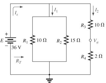
Fig. 7.71
Expert Solution & Answer

Trending nowThis is a popular solution!

Learn your wayIncludes step-by-step video

schedule04:01
Students have asked these similar questions
Don't use ai to answer I will report you answer
592
3.44 Use mesh analysis to obtain i, in the circuit of
Fig. 3.90.
ΖΩ
www
ww
ོག་
6 V
+
www
492
192
ww
3 A
+
12 V
Don't use ai to answer I will report you answer
Chapter 7 Solutions
Laboratory Manual for Introductory Circuit Analysis
Ch. 7 - Which elements (individual elements, not...Ch. 7 - Repeat Problem 1 for the networks of Fig. 7.65....Ch. 7 - Determine RT for the networks in Fig. 7.66. Fig....Ch. 7 - Determine RT for the networks in Fig. 7.67. Fig....Ch. 7 - Find the total resistance for the configuration of...Ch. 7 - The total resistance RT for the network of Fig....Ch. 7 - For the network in Fig. 7.70. a. Does...Ch. 7 - For the network in Fig. 7.71: a. Determine RT. b....Ch. 7 - For the network of Fig. 7.72: a. find the currents...Ch. 7 - For the network of Fig. 7.73: Find the voltages V3...
Ch. 7 - For the network of Fig. 7.74 a. Find the voltages...Ch. 7 - For the circuit board in Fig. 7.75: Find the total...Ch. 7 - Find the value of each resistor for the network of...Ch. 7 - Find the resistance RT for the network of Fig....Ch. 7 - For the network in Fig. 7.78: a. Find currents...Ch. 7 - a. Find the magnitude and direction of the...Ch. 7 - Determine the currents I1andI2 for the network in...Ch. 7 - For the network in Fig. 7.81: a. Determine the...Ch. 7 - For the network in Fig. 7.82: a. Determine the...Ch. 7 - Determine the dc levels for the transistor network...Ch. 7 - For the network in Fig. 7.84: Determine the...Ch. 7 - For the network in Fig. 7.852 Determine RT by...Ch. 7 - For the network of Fig. 7.86: a. Find the voltages...Ch. 7 - For the network in Fig. 7.87: a. Determine the...Ch. 7 - For the network in Fig. 7.88 find the resistance...Ch. 7 - If all the resistors of the cube in Fig. 7.89 are...Ch. 7 - For the ladder network in Fig. 7.90: a. Find the...Ch. 7 - For the ladder network in Fig. 7.91: a. Determine...Ch. 7 - Given the voltage divider supply in Fig. 7.92: a....Ch. 7 - Determine the voltage divider supply resistors for...Ch. 7 - A studio lamp requires 40 V at 50 mA to burn...Ch. 7 - For the system in Fig. 7.94 a. At first exposure,...Ch. 7 - For the potentiometer in Fig. 7.95: a. What are...Ch. 7 - Prob. 34PCh. 7 - Given the voltmeter reading V = 27 V in Fig. 7.97...Ch. 7 - Determine the power delivered to the 6 load in...Ch. 7 - For the multiple ladder configuration in Fig....Ch. 7 - An iron-vane movement is rated 1 mA, 100 . a. What...Ch. 7 - Using a 50 A, 1000 movement, design a multirange...Ch. 7 - An iron-vane movement is rated 50 A , 1000 a....Ch. 7 - Using a 1 mA, 1000 movement, design a multirange...Ch. 7 - A digital meter has an internal resistance of 10 M...Ch. 7 - a. Design a series ohmmeter using a 100 A, 1000...Ch. 7 - Prob. 44PCh. 7 - Determine the reading of the ohmmeter for each...Ch. 7 - Using PSpice or Multisim, verify the result of...Ch. 7 - Using PSpice or Multisim, Confirm the solutions of...Ch. 7 - Using PSpice or Multisim, verify the result of...Ch. 7 - Using PSpice or Multisim, find voltage V6 of Fig....Ch. 7 - Using PSpice or Multisim, find voltages Vb and Vc...
Additional Engineering Textbook Solutions
Find more solutions based on key concepts
Determine the reactions at the supports A and B, then draw the shear and moment diagrams. El is constant.
Mechanics of Materials (10th Edition)
Fill in the blanks in each of the following statements: A relation that has no partial functional dependencies ...
Modern Database Management
What are the two primary stack operations? Describe them both.
Starting Out with C++ from Control Structures to Objects (9th Edition)
Big data Big data describes datasets with huge volumes that are beyond the ability of typical database manageme...
Management Information Systems: Managing The Digital Firm (16th Edition)
The ____________ is always transparent.
Web Development and Design Foundations with HTML5 (8th Edition)
What is the difference between open-cell and closed-cell foamed plastics?
Degarmo's Materials And Processes In Manufacturing
Knowledge Booster


Learn more about
Need a deep-dive on the concept behind this application? Look no further. Learn more about this topic, electrical-engineering and related others by exploring similar questions and additional content below.Similar questions
- 2. If the Ce value in Fig. 11-7 is changed to 0.1 μF, is the output still a PWM waveform? Explain. C₁ 0.014 C₂ 100 R₁ 300 HF 8 Vcc 4 reset output 3 discharge 7 2 trigger 5 control voltage U₁ LM555 6 threshold GND ODUCT R₂ 10k ww Bo +12 V 22 R3 1k VR 5k www Re 300 C5 100 ww 8 Vcc 4 reset output 3 2 trigger 7 discharge ли R7 10k PWM Output threshold C6 -0.014 5 control voltage GND Rs 2k CA U2 LM555 1 100μ C3 0.01 Audio lutput Fig. 11-7 Pulse width modulatorarrow_forwardPROD 1. What is the function of VR, in Figs. 11-2 and 11-7. DL RO 0.014 +12V R₁ 1k ww Vin(+) 6 C₁ 0.1μ Audio input HH VRI Vin(-) 4 U1 HА741 10k ww R2 10k UCTS 0.01 μ -12V PWM output Fig. 11-2 The pulse width modulator based on μA741 +12 V ° C₂ 100 R₁ 300 Re 300 Cs 100 ww ww Vcc 4 reset 2 trigger 5 control voltage U₁ LM555 GND www R₂ T₁ 10k output 3 discharge Z Voc output 3 reset VR₁ 5k 2 trigger 7 discharge Ra 1k threshold 6 control 6 threshold voltage GND Rs CA U2 LM555 1 2k 100 Ca 0.01 Audio lutput www R7 10k O PWM C6 -0.014 Fig. 11-7 Pulse width modulator 11/9 Outputarrow_forwardPRO3. In a point of view of voltage polarity, what is the difference between the output PWM signals in experiments 11-1 and 11-2? H ICTS Experiment 11-1.. Pulse Width Modulator Using uA741 Experiment 11-2 Pulse Width Modulator Using LM555arrow_forward
- 9.58 Using Fig. 9.65, design a problem to help other ed students better understand impedance combinations. Figure 8 65 ww C L R₁ www R2arrow_forwardindicate which of the following switches may be used to control the loads listedarrow_forwardEXAMPLE 3.15 Consider a sinusoidal signal g(t) = Acos (2лfot+), where the parameters A, fo, and are nonzero constants representing the amplitude, frequency, and initial phase of the sinusoidal signal, respectively. Determine if it is an energy signal or a power signal or neither.arrow_forward
- Do part a,b,c and earrow_forward9.69 Find the equivalent admittance Yea of the circuit in Fig. 9.76. 2S 1 S -j3 S -j2 S www ww m m j5 S j1 S www 4 Sarrow_forward9.60 Obtain Zin for the circuit in Fig. 9.67. Zin 25 Ω www Figure 9.67 For Prob. 9.60. j152 m -j500 20 Ω 61 Find in the of Fia 0.68 m 30 Ω j102arrow_forward
- Figure 9.58 For Prob. 9.51. 9.52 If V. =8/30° V in the circuit of Fig. 9.59, find I¸. Is 4 10 Ω Figure 9.59 For Prob. 9.52. www -j5Q 5 Ω ww j5Q Voarrow_forward9.64 Find ZT and I in the circuit in Fig. 9.71. 30/90° V 492 www 602 www N ZT (+) Figure 9.71 For Prob. 9.64. -j10 18 Ωarrow_forward(b) 10 i dt + +6i(t) = 5 cos(5t + 22°) A dt 9.26 The loop equation for a series RLC circuit gives di+2i+ [ i dt = cos 21 A Assuming that the value of the integral at t=-00 is zero, find i(t) using the phasor method. 50 Figure 9arrow_forward
arrow_back_ios
SEE MORE QUESTIONS
arrow_forward_ios
Recommended textbooks for you
 Introductory Circuit Analysis (13th Edition)Electrical EngineeringISBN:9780133923605Author:Robert L. BoylestadPublisher:PEARSON
 Delmar's Standard Textbook Of ElectricityElectrical EngineeringISBN:9781337900348Author:Stephen L. HermanPublisher:Cengage Learning
 Programmable Logic ControllersElectrical EngineeringISBN:9780073373843Author:Frank D. PetruzellaPublisher:McGraw-Hill Education
 Fundamentals of Electric CircuitsElectrical EngineeringISBN:9780078028229Author:Charles K Alexander, Matthew SadikuPublisher:McGraw-Hill Education
 Electric Circuits. (11th Edition)Electrical EngineeringISBN:9780134746968Author:James W. Nilsson, Susan RiedelPublisher:PEARSON
 Engineering ElectromagneticsElectrical EngineeringISBN:9780078028151Author:Hayt, William H. (william Hart), Jr, BUCK, John A.Publisher:Mcgraw-hill Education,
Introductory Circuit Analysis (13th Edition)
Electrical Engineering
ISBN:9780133923605
Author:Robert L. Boylestad
Publisher:PEARSON
Delmar's Standard Textbook Of Electricity
Electrical Engineering
ISBN:9781337900348
Author:Stephen L. Herman
Publisher:Cengage Learning
Programmable Logic Controllers
Electrical Engineering
ISBN:9780073373843
Author:Frank D. Petruzella
Publisher:McGraw-Hill Education
Fundamentals of Electric Circuits
Electrical Engineering
ISBN:9780078028229
Author:Charles K Alexander, Matthew Sadiku
Publisher:McGraw-Hill Education
Electric Circuits. (11th Edition)
Electrical Engineering
ISBN:9780134746968
Author:James W. Nilsson, Susan Riedel
Publisher:PEARSON
Engineering Electromagnetics
Electrical Engineering
ISBN:9780078028151
Author:Hayt, William H. (william Hart), Jr, BUCK, John A.
Publisher:Mcgraw-hill Education,
Current Divider Rule; Author: Neso Academy;https://www.youtube.com/watch?v=hRU1mKWUehY;License: Standard YouTube License, CC-BY