
Concept explainers
Videos
(a)
The points where the shearing stress is maximum and the values of the stress.
(a)
Answer to Problem 80P
The shearing stress is maximum at the points of
The maximum shear stress along the vertical leg is
The maximum shear stress along the horizontal leg is
The maximum shear stress at the corner of the leg is
Explanation of Solution
Calculation:
Refer to sample problem 6.6 in the text book.
Combined stress along the vertical leg
Combined stress along the horizontal leg
Modify Equation (1).
Calculate the point along the vertical leg differentiate both sides of the equation with respect to y as shown below.
Consider the condition
Hence, the shearing stress is maximum at the points of
Calculate the maximum shear stress along the vertical leg as shown below.
Substitute
Hence, the maximum shear stress along the vertical leg is
Modify Equation (2).
Calculate the point along the horizontal leg differentiate both sides of the equation with respect to z as shown below.
Consider the condition
Hence, the shearing stress is maximum at the points of
Calculate the maximum shear stress along the horizontal leg as shown below.
Substitute
Hence, the maximum shear stress along the horizontal leg is
The corner points of the horizontal and vertical legs are
Calculate the maximum shear stress at the corner point as shown below.
Substitute 0 for y in Equation (1).
Substitute 0 for z in Equation (2).
Therefore, the maximum shear stress at the corner of the leg is
(b)
Show that the points are located on the neutral axis for the loading P.
(b)
Answer to Problem 80P
The points y and z are located on the neutral axis for the loading P.
Explanation of Solution
Calculation:
Sketch the cross section along the neutral axis as shown below.
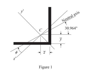
Refer to Figure 1.
Calculate the moment of inertia as shown below.
Along
Along
Consider the angle
Calculate angle
Substitute
Calculate the angle of the neutral axis from the horizontal as shown below.
Calculate the location of the centroid as shown below.
Along y axis:
Along z axis:
Calculate the neutral axis intersects for vertical leg as shown below.
Substitute
Calculate the neutral axis intersects for horizontal leg as shown below.
Substitute
Therefore, the points y and z are located on the neutral axis for the loading P
Want to see more full solutions like this?
Chapter 6 Solutions
Mechanics of Materials, 7th Edition


- Auto Controls A union feedback control system has the following open loop transfer function where k>0 is a variable proportional gain i. for K = 1 , derive the exact magnitude and phase expressions of G(jw). ii) for K = 1 , identify the gaincross-over frequency (Wgc) [where IG(jo))| 1] and phase cross-overfrequency [where <G(jw) = - 180]. You can use MATLAB command "margin" to obtain there quantities. iii) Calculate gain margin (in dB) and phase margin (in degrees) ·State whether the closed-loop is stable for K = 1 and briefly justify your answer based on the margin . (Gain marginPhase margin) iv. what happens to the gain margin and Phase margin when you increase the value of K?you You can use for loop in MATLAB to check that.Helpful matlab commands : if, bode, margin, rlocus NO COPIED SOLUTIONSarrow_forwardThe 120 kg wheel has a radius of gyration of 0.7 m. A force P with a magnitude of 50 N is applied at the edge of the wheel as seen in the diagram. The coefficient of static friction is 0.3, and the coefficient of kinetic friction is 0.25. Find the acceleration and angular acceleration of the wheel.arrow_forwardAuto Controls Using MATLAB , find the magnitude and phase plot of the compensators NO COPIED SOLUTIONSarrow_forward
- 4-81 The corner shown in Figure P4-81 is initially uniform at 300°C and then suddenly exposed to a convection environment at 50°C with h 60 W/m². °C. Assume the = 2 solid has the properties of fireclay brick. Examine nodes 1, 2, 3, 4, and 5 and deter- mine the maximum time increment which may be used for a transient numerical calculation. Figure P4-81 1 2 3 4 1 cm 5 6 1 cm 2 cm h, T + 2 cmarrow_forwardAuto Controls A union feedback control system has the following open loop transfer function where k>0 is a variable proportional gain i. for K = 1 , derive the exact magnitude and phase expressions of G(jw). ii) for K = 1 , identify the gaincross-over frequency (Wgc) [where IG(jo))| 1] and phase cross-overfrequency [where <G(jw) = - 180]. You can use MATLAB command "margin" to obtain there quantities. iii) Calculate gain margin (in dB) and phase margin (in degrees) ·State whether the closed-loop is stable for K = 1 and briefly justify your answer based on the margin . (Gain marginPhase margin) iv. what happens to the gain margin and Phase margin when you increase the value of K?you You can use for loop in MATLAB to check that.Helpful matlab commands : if, bode, margin, rlocus NO COPIED SOLUTIONSarrow_forwardAuto Controls Hand sketch the root Focus of the following transfer function How many asymptotes are there ?what are the angles of the asymptotes?Does the system remain stable for all values of K NO COPIED SOLUTIONSarrow_forward
- Please draw the section view of the following problemsarrow_forward7) Please draw the front, top and side view for the following object. Please cross this line outarrow_forwardA 10-kg box is pulled along P,Na rough surface by a force P, as shown in thefigure. The pulling force linearly increaseswith time, while the particle is motionless att = 0s untilit reaches a maximum force of100 Nattimet = 4s. If the ground has staticand kinetic friction coefficients of u, = 0.6 andHU, = 0.4 respectively, determine the velocityof the A 1 0 - kg box is pulled along P , N a rough surface by a force P , as shown in the figure. The pulling force linearly increases with time, while the particle is motionless at t = 0 s untilit reaches a maximum force of 1 0 0 Nattimet = 4 s . If the ground has static and kinetic friction coefficients of u , = 0 . 6 and HU , = 0 . 4 respectively, determine the velocity of the particle att = 4 s .arrow_forward
 Elements Of ElectromagneticsMechanical EngineeringISBN:9780190698614Author:Sadiku, Matthew N. O.Publisher:Oxford University Press
 Mechanics of Materials (10th Edition)Mechanical EngineeringISBN:9780134319650Author:Russell C. HibbelerPublisher:PEARSON
 Thermodynamics: An Engineering ApproachMechanical EngineeringISBN:9781259822674Author:Yunus A. Cengel Dr., Michael A. BolesPublisher:McGraw-Hill Education
 Control Systems EngineeringMechanical EngineeringISBN:9781118170519Author:Norman S. NisePublisher:WILEY
 Mechanics of Materials (MindTap Course List)Mechanical EngineeringISBN:9781337093347Author:Barry J. Goodno, James M. GerePublisher:Cengage Learning
 Engineering Mechanics: StaticsMechanical EngineeringISBN:9781118807330Author:James L. Meriam, L. G. Kraige, J. N. BoltonPublisher:WILEY