
VECTOR MECH...,STAT.+DYN.(LL)-W/ACCESS
12th Edition
ISBN: 9781260265453
Author: BEER
Publisher: MCG
expand_more
expand_more
format_list_bulleted
Videos
Textbook Question
Chapter 6.4, Problem 6.130P
The pin at B is attached to member ABC and can slide freely along the slot cut in the fixed plate. Neglecting the effect of friction, determine the couple M required to hold the system in equilibrium when θ = 60°.
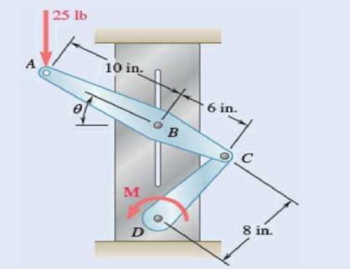
Fig. P6.129 and P6.130
Expert Solution & Answer
Want to see the full answer?
Check out a sample textbook solution
Students have asked these similar questions
A simply supported T-shaped beam of 6m in length has to be
designed to carry an inclined central point load W. Find the max-
imum value of this load such that the maximum tensile and com-
pression stresses on the beam do not exceed 30 and 60
respectively.
N
mm²
N
mm²,
90 mm
80 mm
Y
W
60 mm
30°
10 mm
10 mm
X
Problem 9.5
9.5 A 1080-kg car is parked on a sloped street. The figure shows its wheels and the position of
its center of mass. The street is icy, and as a result the coefficient of static friction between
the car's tires and the street surface is μs = 0.2. Determine the steepest slope (in degrees
relative to the horizontal) at which the car could remain in equilibrium if
a. the brakes are applied to both its front and rear wheels;
b. the brakes are applied to the front (lower) wheels only.
Problem 9.5
1380 mm
532 mm
2370 mm
Can someone explain please with conversions
Chapter 6 Solutions
VECTOR MECH...,STAT.+DYN.(LL)-W/ACCESS
Ch. 6.1 - Using the method of joints, determine the force in...Ch. 6.1 - Using the method of joints, determine the force in...Ch. 6.1 - Using the method of joints, determine the force in...Ch. 6.1 - Using the method of joints, determine the force in...Ch. 6.1 - Using the method of joints, determine the force in...Ch. 6.1 - Using the method of joints, determine the force in...Ch. 6.1 - Using the method of joints, determine the force in...Ch. 6.1 - Using the method of joints, determine the force in...Ch. 6.1 - Using the method of joints, determine the force in...Ch. 6.1 - Determine the force in each member of the truss...
Ch. 6.1 - Determine the force in each member of the Gambrel...Ch. 6.1 - Determine the force in each member of the Howe...Ch. 6.1 - Using the method of joints, determine the force in...Ch. 6.1 - Using the method of joints, determine the force in...Ch. 6.1 - Determine the force in each member of the Warren...Ch. 6.1 - Solve Problem 6.15 assuming that the load applied...Ch. 6.1 - Determine the force in each member of the Pratt...Ch. 6.1 - The truss shown is one of several supporting an...Ch. 6.1 - Determine the force in each member of the Pratt...Ch. 6.1 - Prob. 6.20PCh. 6.1 - Determine the force in each of the members located...Ch. 6.1 - Determine the force in member DE and in each of...Ch. 6.1 - Determine the force in each of the members located...Ch. 6.1 - The portion of truss shown represents the upper...Ch. 6.1 - For the tower and loading of Prob. 6.24 and...Ch. 6.1 - Solve Problem 6.24 assuming that the cables...Ch. 6.1 - Determine the force in each member of the truss...Ch. 6.1 - Determine the force in each member of the truss...Ch. 6.1 - Determine whether the trusses of Problems 6.31a,...Ch. 6.1 - Determine whether the trusses of Problems 6.31b,...Ch. 6.1 - For the given loading, determine the zero-force...Ch. 6.1 - Prob. 6.32PCh. 6.1 - For the given loading, determine the zero-force...Ch. 6.1 - Prob. 6.34PCh. 6.1 - Prob. 6.35PCh. 6.1 - Prob. 6.36PCh. 6.1 - The truss shown consists of six members and is...Ch. 6.1 - The truss shown consists of nine members and is...Ch. 6.1 - The truss shown consists of nine members and is...Ch. 6.1 - Solve Prob. 6.39 for P = 0 and Q = (900 N)k. 6.39...Ch. 6.1 - The truss shown consists of 18 members and is...Ch. 6.1 - The truss shown consists of 18 members and is...Ch. 6.2 - Determine the force in members BD and DE of the...Ch. 6.2 - Determine the force in members DG and EG of the...Ch. 6.2 - Determine the force in members BD and CD of the...Ch. 6.2 - Determine the force in members DF and DG of the...Ch. 6.2 - A floor truss is loaded as shown. Determine the...Ch. 6.2 - A floor truss is loaded as shown. Determine the...Ch. 6.2 - Determine the force in members CD and DF of the...Ch. 6.2 - Determine the force in members CE and EF of the...Ch. 6.2 - Determine the force in members DE and DF of the...Ch. 6.2 - Prob. 6.52PCh. 6.2 - Determine the force in members DF and DE of the...Ch. 6.2 - Prob. 6.54PCh. 6.2 - A Pratt roof truss is loaded as shown. Determine...Ch. 6.2 - A Pratt roof truss is loaded as shown. Determine...Ch. 6.2 - A Howe scissors roof truss is loaded as shown....Ch. 6.2 - A Howe scissors roof truss is loaded as shown....Ch. 6.2 - Determine the force in members AD, CD, and CE of...Ch. 6.2 - Determine the force in members DG, FG, and FH of...Ch. 6.2 - Determine the force in member GJ of the truss...Ch. 6.2 - Determine the force in members DG and FH of the...Ch. 6.2 - Determine the force in members CD and JK of the...Ch. 6.2 - Determine the force in members DE and KL of the...Ch. 6.2 - The diagonal members in the center panels of the...Ch. 6.2 - The diagonal members in the center panels of the...Ch. 6.2 - Prob. 6.67PCh. 6.2 - Prob. 6.68PCh. 6.2 - Classify each of the structures shown as...Ch. 6.2 - Classify each of the structures shown as...Ch. 6.2 - Prob. 6.71PCh. 6.2 - 6.70 through 6.74 classify as determinate or...Ch. 6.2 - 6.70 through 6.74 classify as determinate or...Ch. 6.2 - 6.70 through 6.74 classify as determinate or...Ch. 6.3 - For the frame and loading shown, draw the...Ch. 6.3 - For the frame and loading shown, draw the...Ch. 6.3 - Draw the free-body diagram(s) needed to determine...Ch. 6.3 - Knowing that the pulley has a radius of 0.5 m,...Ch. 6.3 - and 6.76 Determine the force in member BD and the...Ch. 6.3 - and 6.76 Determine the force in member BD and the...Ch. 6.3 - For the frame and loading shown, determine the...Ch. 6.3 - Determine the components of all forces acting on...Ch. 6.3 - The hydraulic cylinder CF, which partially...Ch. 6.3 - The hydraulic cylinder CF, which partially...Ch. 6.3 - Determine the components of all forces acting on...Ch. 6.3 - Determine the components of all forces acting on...Ch. 6.3 - Determine the components of the reactions at A and...Ch. 6.3 - Determine the components of the reactions at D and...Ch. 6.3 - Determine the components of the reactions at A and...Ch. 6.3 - Determine the components of the reactions at A and...Ch. 6.3 - Prob. 6.87PCh. 6.3 - The 48-lb load can be moved along the line of...Ch. 6.3 - The 48-lb load is removed and a 288-lb in....Ch. 6.3 - (a) Show that, when a frame supports a pulley at...Ch. 6.3 - Knowing that each pulley has a radius of 250 mm,...Ch. 6.3 - Knowing that the pulley has a radius of 75 mm,...Ch. 6.3 - Two 9-in.-diameter pipes (pipe 1 and pipe 2) are...Ch. 6.3 - Prob. 6.94PCh. 6.3 - Prob. 6.95PCh. 6.3 - Prob. 6.96PCh. 6.3 - Prob. 6.97PCh. 6.3 - Prob. 6.98PCh. 6.3 - Knowing that P = 90 lb and Q = 60 lb, determine...Ch. 6.3 - Knowing that P = 90 lb and Q = 60 lb, determine...Ch. 6.3 - For the frame and loading shown, determine the...Ch. 6.3 - For the frame and loading shown, determine the...Ch. 6.3 - Knowing that P = 15 lb and Q = 65 lb, determine...Ch. 6.3 - Knowing that P = 25 lb and Q = 55 lb, determine...Ch. 6.3 - For the frame and loading shown, determine the...Ch. 6.3 - Prob. 6.106PCh. 6.3 - The axis of the three-hinge arch ABC is a parabola...Ch. 6.3 - The axis of the three-hinge arch ABC is a parabola...Ch. 6.3 - Prob. 6.109PCh. 6.3 - Prob. 6.110PCh. 6.3 - 6.111, 6.112, and 6.113 Members ABC and CDE are...Ch. 6.3 - Prob. 6.112PCh. 6.3 - 6.111, 6.112, and 6.113 Members ABC and CDE are...Ch. 6.3 - Members ABC and CDE are pin-connected at C and...Ch. 6.3 - Solve Prob. 6.112 assuming that the force P is...Ch. 6.3 - Solve Prob. 6.114 assuming that the force P is...Ch. 6.3 - Prob. 6.117PCh. 6.3 - Prob. 6.118PCh. 6.3 - 6.119 through 6.121 Each of the frames shown...Ch. 6.3 - 6.119 through 6.121 Each of the frames shown...Ch. 6.3 - 6.119 through 6.121 Each of the frames shown...Ch. 6.4 - An 84-lb force is applied to the toggle vise at C....Ch. 6.4 - For the system and loading shown, draw the...Ch. 6.4 - Prob. 6.7FBPCh. 6.4 - The position of member ABC is controlled by the...Ch. 6.4 - The shear shown is used to cut and trim...Ch. 6.4 - A 100-lb force directed vertically downward is...Ch. 6.4 - Prob. 6.124PCh. 6.4 - The control rod CE passes through a horizontal...Ch. 6.4 - Solve Prob. 6.125 when (a) = 0, (b) = 6. Fig....Ch. 6.4 - The press shown is used to emboss a small seal at...Ch. 6.4 - The press shown is used to emboss a small seal at...Ch. 6.4 - Prob. 6.129PCh. 6.4 - The pin at B is attached to member ABC and can...Ch. 6.4 - Arm ABC is connected by pins to a collar at B and...Ch. 6.4 - Arm ABC is connected by pins to a collar at B and...Ch. 6.4 - The Whitworth mechanism shown is used to produce a...Ch. 6.4 - Prob. 6.134PCh. 6.4 - and 6.136 Two rods are connected by a slider block...Ch. 6.4 - and 6.136 Two rods are connected by a slider block...Ch. 6.4 - 6.137 and 6.138 Rod CD is attached to the collar D...Ch. 6.4 - 6.137 and 6.138 Rod CD is attached to the collar D...Ch. 6.4 - Two hydraulic cylinders control the position of...Ch. 6.4 - Prob. 6.140PCh. 6.4 - A steel ingot weighing 8000 lb is lifted by a pair...Ch. 6.4 - If the toggle shown is added to the tongs of Prob....Ch. 6.4 - A 9-m length of railroad rail of mass 40 kg/m is...Ch. 6.4 - Prob. 6.144PCh. 6.4 - The pliers shown are used to grip a...Ch. 6.4 - Prob. 6.146PCh. 6.4 - In using the bolt cutter shown, a worker applies...Ch. 6.4 - The upper blade and lower handle of the...Ch. 6.4 - Prob. 6.149PCh. 6.4 - and 6.150 Determine the force P that must be...Ch. 6.4 - Prob. 6.151PCh. 6.4 - Prob. 6.152PCh. 6.4 - The elevation of the platform is controlled by two...Ch. 6.4 - For the frame and loading shown, determine the...Ch. 6.4 - The telescoping arm ABC is used to provide an...Ch. 6.4 - The telescoping arm ABC of Prob. 6.155 can be...Ch. 6.4 - The motion of the backhoe bucket shown is...Ch. 6.4 - Prob. 6.158PCh. 6.4 - The gears A and D are rigidly attached to...Ch. 6.4 - In the planetary gear system shown, the radius of...Ch. 6.4 - Two shafts AC and CF, which lie in the vertical xy...Ch. 6.4 - Two shafts AC and CF, which lie in the vertical xy...Ch. 6.4 - The large mechanical tongs shown are used to grab...Ch. 6 - Using the method of joints, determine the force in...Ch. 6 - Using the method of joints, determine the force in...Ch. 6 - A stadium roof truss is loaded as shown. Determine...Ch. 6 - A stadium roof truss is loaded as shown. Determine...Ch. 6 - Determine the components of all forces acting on...Ch. 6 - Prob. 6.169RPCh. 6 - Knowing that the pulley has a radius of 50 mm,...Ch. 6 - For the frame and loading shown, determine the...Ch. 6 - For the frame and loading shown, determine the...Ch. 6 - Water pressure in the supply system exerts a...Ch. 6 - A couple M with a magnitude of 1.5 kNm is applied...Ch. 6 - Prob. 6.175RP
Knowledge Booster


Learn more about
Need a deep-dive on the concept behind this application? Look no further. Learn more about this topic, mechanical-engineering and related others by exploring similar questions and additional content below.Similar questions
- Correct Answer is written below. Detailed and complete fbd only please. I will upvote, thank you. 1: The assembly shown is composed of a rigid plank ABC, supported by hinge at A, spring at B and cable at C.The cable is attached to a frictionless pulley at D and rigidly supported at E. The cable is made of steel with E = 200,000MPa and cross-sectional area of 500 mm2. The details of pulley at D is shown. The pulley is supported by a pin, passingthough the pulley and attached to both cheeks. Note that E is directly above B.Given: H = 3 m; L1 = 2 m; L2 = 4 m; w = 12 kN/m; x:y = 3:4Spring Parameters:Wire diameter = 30 mmMean Radius = 90 mmNumber of turns = 12Modulus of Rigidity = 80 GPaAllowable stresses:Allowable shear stress of Pin at D = 85 MPaAllowable normal stress of cheek at D = 90MPaAllowable bearing stress of cheek at D = 110MPa1. Calculate the reaction of spring Band tension in cable at C.2. Calculate the vertical displacementat C and the required diameter ofpin at D.3.…arrow_forwardCorrect answer and complete fbd only. I will upvote. The compound shaft, composed of steel,aluminum, and bronze segments, carries the two torquesshown in the figure. If TC = 250 lb-ft, determine the maximumshear stress developed in each material (in ksi). The moduliof rigidity for steel, aluminum, and bronze are 12 x 106 psi, 4x 10⁶ psi, and 6 x 10⁶ psi, respectivelyarrow_forwardCan you explain the algebra steps that aren't shown but stated to be there, on how to get this equationarrow_forward
- Correct answer and complete fbd only. I will upvote. A flanged bolt coupling consists of two concentric rows of bolts. The inner row has 6 nos. of 16mm diameterbolts spaced evenly in a circle of 250mm in diameter. The outer row of has 10 nos. of 25 mm diameter bolts spaced evenly in a circle of 500mm in diameter. If the allowable shear stress on one bolt is 60 MPa, determine the torque capacity of the coupling. The Poisson’s ratio of the inner row of bolts is 0.2 while that of the outer row is 0.25 and the bolts are steel, E =200 GPa.arrow_forwardCorrect answer and complete fbd only. I will upvote. 10: The constant wall thickness of a steel tube with the cross sectionshown is 2 mm. If a 600-N-m torque is applied to the tube. Use G = 80 GPa forsteel.1. Find the shear stress (MPa) in the wall of the tube.2. Find the angle of twist, in degrees per meter of length.arrow_forwardCORRECT ANSWER WITH COMPLETE FBD ONLY. I WILL UPVOTE. A torque wrench is used to tighten the pipe shown.Dimensions: S1 = 400 mm; S2 = 250 mm; S3 = 100 mmModulus of Rigidity G = 78 GPa1. The diameter of the solid pipe is 20 mm. How much is themaximum force P (N) that can be applied based on theallowable shear stress of 60 MPa?2. For a hollow pipe with 50 mm outside diameter and is 6 mmthick, compute for the maximum force P (kN) that can beapplied such that the angle of twist at A does not exceed 5degrees.3. The torque applied to tighten the hollow pipe is 200 N-m.Given: Pipe outside diameter = 50 mm Pipe thickness = 6 mmSolve for the resulting maximum shear stress (MPa) in the pipe.arrow_forward
- Correct answer and complete fbd only. I will upvote. 6: The shaft carries a total torque T0 that is uniformly distributedover its length L. Determine the angle of twist (degrees) of the shaft in termsif T0 = 1.2 kN-m, L = 2 m, G = 80 GPa, and diameter = 120 mm.arrow_forward2. Calculate the force in all members of the trusses shown using the method of joints. A 5525 lb C 3500 lb BY 14'-0" D 10'- 0" 6250 lb 10'- 0" Earrow_forwardCorrect answer and complete fbd only. I will upvote. 8: The steel rod fits loosely inside the aluminum sleeve. Both components are attached to a rigid wall at A andjoined together by a pin at B. Because of a slight misalignmentof the pre-drilled holes, the torque T0 = 750 N-m was appliedto the steel rod before the pin could be inserted into theholes. Determine the torque (N-m) in each component afterT0 was removed. Use G = 80 GPa for steel and G = 28 GPa foraluminumarrow_forward
- Correct answer and complete fbd only. I will upvote. 9: The two steel shafts, each with one end builtinto a rigid support, have flanges attached to their freeends. The flanges are to be bolted together. However,initially there is a 6⁰ mismatch in the location of the boltholes as shown in the figure. Determine the maximumshear stress(ksi) in each shaft after the flanges have beenbolted together. The shear modulus of elasticity for steelis 12 x 106 psi. Neglect deformations of the bolts and theflanges.arrow_forwardCorrect answer and complete fbd only. I will upvote. The tapered, wrought iron shaft carriesthe torque T = 2000 lb-in at its free end. Determine theangle of twist (degrees) of the shaft. Use G = 10 x 106psi for wrought ironarrow_forwardCorrect answer and complete fbd only. I will upvote. The compound shaft, consisting of steel and aluminumsegments, carries the two torques shown in the figure. Determine themaximum permissible value of T subject to the following designconditions: τst ≤ 83 MPa, τal ≤ 55 MPa, and θ ≤ 6⁰ (θ is the angle ofrotation of the free end). Use G =83 GPa for steel and G = 28 GPa foraluminum.arrow_forward
arrow_back_ios
SEE MORE QUESTIONS
arrow_forward_ios
Recommended textbooks for you
 Elements Of ElectromagneticsMechanical EngineeringISBN:9780190698614Author:Sadiku, Matthew N. O.Publisher:Oxford University Press
 Mechanics of Materials (10th Edition)Mechanical EngineeringISBN:9780134319650Author:Russell C. HibbelerPublisher:PEARSON
 Thermodynamics: An Engineering ApproachMechanical EngineeringISBN:9781259822674Author:Yunus A. Cengel Dr., Michael A. BolesPublisher:McGraw-Hill Education
 Control Systems EngineeringMechanical EngineeringISBN:9781118170519Author:Norman S. NisePublisher:WILEY
 Mechanics of Materials (MindTap Course List)Mechanical EngineeringISBN:9781337093347Author:Barry J. Goodno, James M. GerePublisher:Cengage Learning
 Engineering Mechanics: StaticsMechanical EngineeringISBN:9781118807330Author:James L. Meriam, L. G. Kraige, J. N. BoltonPublisher:WILEY
Elements Of Electromagnetics
Mechanical Engineering
ISBN:9780190698614
Author:Sadiku, Matthew N. O.
Publisher:Oxford University Press
Mechanics of Materials (10th Edition)
Mechanical Engineering
ISBN:9780134319650
Author:Russell C. Hibbeler
Publisher:PEARSON
Thermodynamics: An Engineering Approach
Mechanical Engineering
ISBN:9781259822674
Author:Yunus A. Cengel Dr., Michael A. Boles
Publisher:McGraw-Hill Education
Control Systems Engineering
Mechanical Engineering
ISBN:9781118170519
Author:Norman S. Nise
Publisher:WILEY
Mechanics of Materials (MindTap Course List)
Mechanical Engineering
ISBN:9781337093347
Author:Barry J. Goodno, James M. Gere
Publisher:Cengage Learning
Engineering Mechanics: Statics
Mechanical Engineering
ISBN:9781118807330
Author:James L. Meriam, L. G. Kraige, J. N. Bolton
Publisher:WILEY
Differences between Temporary Joining and Permanent Joining.; Author: Academic Gain Tutorials;https://www.youtube.com/watch?v=PTr8QZhgXyg;License: Standard Youtube License