
VECTOR MECH...,STAT.+DYN.(LL)-W/ACCESS
12th Edition
ISBN: 9781260265453
Author: BEER
Publisher: MCG
expand_more
expand_more
format_list_bulleted
Concept explainers
Videos
Textbook Question
Chapter 6.1, Problem 6.3P
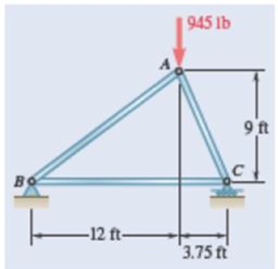
Using the method of joints, determine the force in each member of the truss shown. State whether each member is in tension or compression.
Expert Solution & Answer
Want to see the full answer?
Check out a sample textbook solution
Students have asked these similar questions
A prototype automobile is designed to travel at 65 km/hr. A model of this design is tested in a wind tunnel with identical standard sea-
level air properties at a 1:5 scale. The measured model drag is 529 N, enforcing dynamic similarity. Determine (a) the drag force on the
prototype and (b) the power required to overcome this drag. See the equation
Vm
m
=
D
V Dm
(a) Dp = i
(b) Pp = i
N
hp
A new blimp will move at 6 m/s in 20°C air, and we want to predict the drag force. Using a 1: 14-scale model in water at 20°C and
measuring a 2500-N drag force on the model, determine (a) the required water velocity, (b) the drag on the prototype blimp and, (c) the
power that will be required to propel it through the air.
(a) Vm = i
(b) Dp = i
(c) Pp = i
m/s
N
W
Drag measurements were taken for a sphere, with a diameter of 5 cm, moving at 3.7 m/s in water at 20°C. The resulting drag on the
sphere was 10 N. For a balloon with 1-m diameter rising in air with standard temperature and pressure, determine (a) the velocity if
Reynolds number similarity is enforced and (b) the drag force if the drag coefficient in the equation below is the dependent pi term.
li ε pVI
D
1
= CD = Q
μ
(a) Vp = i
(b) Dp = i
m/s
N
Chapter 6 Solutions
VECTOR MECH...,STAT.+DYN.(LL)-W/ACCESS
Ch. 6.1 - Using the method of joints, determine the force in...Ch. 6.1 - Using the method of joints, determine the force in...Ch. 6.1 - Using the method of joints, determine the force in...Ch. 6.1 - Using the method of joints, determine the force in...Ch. 6.1 - Using the method of joints, determine the force in...Ch. 6.1 - Using the method of joints, determine the force in...Ch. 6.1 - Using the method of joints, determine the force in...Ch. 6.1 - Using the method of joints, determine the force in...Ch. 6.1 - Using the method of joints, determine the force in...Ch. 6.1 - Determine the force in each member of the truss...
Ch. 6.1 - Determine the force in each member of the Gambrel...Ch. 6.1 - Determine the force in each member of the Howe...Ch. 6.1 - Using the method of joints, determine the force in...Ch. 6.1 - Using the method of joints, determine the force in...Ch. 6.1 - Determine the force in each member of the Warren...Ch. 6.1 - Solve Problem 6.15 assuming that the load applied...Ch. 6.1 - Determine the force in each member of the Pratt...Ch. 6.1 - The truss shown is one of several supporting an...Ch. 6.1 - Determine the force in each member of the Pratt...Ch. 6.1 - Prob. 6.20PCh. 6.1 - Determine the force in each of the members located...Ch. 6.1 - Determine the force in member DE and in each of...Ch. 6.1 - Determine the force in each of the members located...Ch. 6.1 - The portion of truss shown represents the upper...Ch. 6.1 - For the tower and loading of Prob. 6.24 and...Ch. 6.1 - Solve Problem 6.24 assuming that the cables...Ch. 6.1 - Determine the force in each member of the truss...Ch. 6.1 - Determine the force in each member of the truss...Ch. 6.1 - Determine whether the trusses of Problems 6.31a,...Ch. 6.1 - Determine whether the trusses of Problems 6.31b,...Ch. 6.1 - For the given loading, determine the zero-force...Ch. 6.1 - Prob. 6.32PCh. 6.1 - For the given loading, determine the zero-force...Ch. 6.1 - Prob. 6.34PCh. 6.1 - Prob. 6.35PCh. 6.1 - Prob. 6.36PCh. 6.1 - The truss shown consists of six members and is...Ch. 6.1 - The truss shown consists of nine members and is...Ch. 6.1 - The truss shown consists of nine members and is...Ch. 6.1 - Solve Prob. 6.39 for P = 0 and Q = (900 N)k. 6.39...Ch. 6.1 - The truss shown consists of 18 members and is...Ch. 6.1 - The truss shown consists of 18 members and is...Ch. 6.2 - Determine the force in members BD and DE of the...Ch. 6.2 - Determine the force in members DG and EG of the...Ch. 6.2 - Determine the force in members BD and CD of the...Ch. 6.2 - Determine the force in members DF and DG of the...Ch. 6.2 - A floor truss is loaded as shown. Determine the...Ch. 6.2 - A floor truss is loaded as shown. Determine the...Ch. 6.2 - Determine the force in members CD and DF of the...Ch. 6.2 - Determine the force in members CE and EF of the...Ch. 6.2 - Determine the force in members DE and DF of the...Ch. 6.2 - Prob. 6.52PCh. 6.2 - Determine the force in members DF and DE of the...Ch. 6.2 - Prob. 6.54PCh. 6.2 - A Pratt roof truss is loaded as shown. Determine...Ch. 6.2 - A Pratt roof truss is loaded as shown. Determine...Ch. 6.2 - A Howe scissors roof truss is loaded as shown....Ch. 6.2 - A Howe scissors roof truss is loaded as shown....Ch. 6.2 - Determine the force in members AD, CD, and CE of...Ch. 6.2 - Determine the force in members DG, FG, and FH of...Ch. 6.2 - Determine the force in member GJ of the truss...Ch. 6.2 - Determine the force in members DG and FH of the...Ch. 6.2 - Determine the force in members CD and JK of the...Ch. 6.2 - Determine the force in members DE and KL of the...Ch. 6.2 - The diagonal members in the center panels of the...Ch. 6.2 - The diagonal members in the center panels of the...Ch. 6.2 - Prob. 6.67PCh. 6.2 - Prob. 6.68PCh. 6.2 - Classify each of the structures shown as...Ch. 6.2 - Classify each of the structures shown as...Ch. 6.2 - Prob. 6.71PCh. 6.2 - 6.70 through 6.74 classify as determinate or...Ch. 6.2 - 6.70 through 6.74 classify as determinate or...Ch. 6.2 - 6.70 through 6.74 classify as determinate or...Ch. 6.3 - For the frame and loading shown, draw the...Ch. 6.3 - For the frame and loading shown, draw the...Ch. 6.3 - Draw the free-body diagram(s) needed to determine...Ch. 6.3 - Knowing that the pulley has a radius of 0.5 m,...Ch. 6.3 - and 6.76 Determine the force in member BD and the...Ch. 6.3 - and 6.76 Determine the force in member BD and the...Ch. 6.3 - For the frame and loading shown, determine the...Ch. 6.3 - Determine the components of all forces acting on...Ch. 6.3 - The hydraulic cylinder CF, which partially...Ch. 6.3 - The hydraulic cylinder CF, which partially...Ch. 6.3 - Determine the components of all forces acting on...Ch. 6.3 - Determine the components of all forces acting on...Ch. 6.3 - Determine the components of the reactions at A and...Ch. 6.3 - Determine the components of the reactions at D and...Ch. 6.3 - Determine the components of the reactions at A and...Ch. 6.3 - Determine the components of the reactions at A and...Ch. 6.3 - Prob. 6.87PCh. 6.3 - The 48-lb load can be moved along the line of...Ch. 6.3 - The 48-lb load is removed and a 288-lb in....Ch. 6.3 - (a) Show that, when a frame supports a pulley at...Ch. 6.3 - Knowing that each pulley has a radius of 250 mm,...Ch. 6.3 - Knowing that the pulley has a radius of 75 mm,...Ch. 6.3 - Two 9-in.-diameter pipes (pipe 1 and pipe 2) are...Ch. 6.3 - Prob. 6.94PCh. 6.3 - Prob. 6.95PCh. 6.3 - Prob. 6.96PCh. 6.3 - Prob. 6.97PCh. 6.3 - Prob. 6.98PCh. 6.3 - Knowing that P = 90 lb and Q = 60 lb, determine...Ch. 6.3 - Knowing that P = 90 lb and Q = 60 lb, determine...Ch. 6.3 - For the frame and loading shown, determine the...Ch. 6.3 - For the frame and loading shown, determine the...Ch. 6.3 - Knowing that P = 15 lb and Q = 65 lb, determine...Ch. 6.3 - Knowing that P = 25 lb and Q = 55 lb, determine...Ch. 6.3 - For the frame and loading shown, determine the...Ch. 6.3 - Prob. 6.106PCh. 6.3 - The axis of the three-hinge arch ABC is a parabola...Ch. 6.3 - The axis of the three-hinge arch ABC is a parabola...Ch. 6.3 - Prob. 6.109PCh. 6.3 - Prob. 6.110PCh. 6.3 - 6.111, 6.112, and 6.113 Members ABC and CDE are...Ch. 6.3 - Prob. 6.112PCh. 6.3 - 6.111, 6.112, and 6.113 Members ABC and CDE are...Ch. 6.3 - Members ABC and CDE are pin-connected at C and...Ch. 6.3 - Solve Prob. 6.112 assuming that the force P is...Ch. 6.3 - Solve Prob. 6.114 assuming that the force P is...Ch. 6.3 - Prob. 6.117PCh. 6.3 - Prob. 6.118PCh. 6.3 - 6.119 through 6.121 Each of the frames shown...Ch. 6.3 - 6.119 through 6.121 Each of the frames shown...Ch. 6.3 - 6.119 through 6.121 Each of the frames shown...Ch. 6.4 - An 84-lb force is applied to the toggle vise at C....Ch. 6.4 - For the system and loading shown, draw the...Ch. 6.4 - Prob. 6.7FBPCh. 6.4 - The position of member ABC is controlled by the...Ch. 6.4 - The shear shown is used to cut and trim...Ch. 6.4 - A 100-lb force directed vertically downward is...Ch. 6.4 - Prob. 6.124PCh. 6.4 - The control rod CE passes through a horizontal...Ch. 6.4 - Solve Prob. 6.125 when (a) = 0, (b) = 6. Fig....Ch. 6.4 - The press shown is used to emboss a small seal at...Ch. 6.4 - The press shown is used to emboss a small seal at...Ch. 6.4 - Prob. 6.129PCh. 6.4 - The pin at B is attached to member ABC and can...Ch. 6.4 - Arm ABC is connected by pins to a collar at B and...Ch. 6.4 - Arm ABC is connected by pins to a collar at B and...Ch. 6.4 - The Whitworth mechanism shown is used to produce a...Ch. 6.4 - Prob. 6.134PCh. 6.4 - and 6.136 Two rods are connected by a slider block...Ch. 6.4 - and 6.136 Two rods are connected by a slider block...Ch. 6.4 - 6.137 and 6.138 Rod CD is attached to the collar D...Ch. 6.4 - 6.137 and 6.138 Rod CD is attached to the collar D...Ch. 6.4 - Two hydraulic cylinders control the position of...Ch. 6.4 - Prob. 6.140PCh. 6.4 - A steel ingot weighing 8000 lb is lifted by a pair...Ch. 6.4 - If the toggle shown is added to the tongs of Prob....Ch. 6.4 - A 9-m length of railroad rail of mass 40 kg/m is...Ch. 6.4 - Prob. 6.144PCh. 6.4 - The pliers shown are used to grip a...Ch. 6.4 - Prob. 6.146PCh. 6.4 - In using the bolt cutter shown, a worker applies...Ch. 6.4 - The upper blade and lower handle of the...Ch. 6.4 - Prob. 6.149PCh. 6.4 - and 6.150 Determine the force P that must be...Ch. 6.4 - Prob. 6.151PCh. 6.4 - Prob. 6.152PCh. 6.4 - The elevation of the platform is controlled by two...Ch. 6.4 - For the frame and loading shown, determine the...Ch. 6.4 - The telescoping arm ABC is used to provide an...Ch. 6.4 - The telescoping arm ABC of Prob. 6.155 can be...Ch. 6.4 - The motion of the backhoe bucket shown is...Ch. 6.4 - Prob. 6.158PCh. 6.4 - The gears A and D are rigidly attached to...Ch. 6.4 - In the planetary gear system shown, the radius of...Ch. 6.4 - Two shafts AC and CF, which lie in the vertical xy...Ch. 6.4 - Two shafts AC and CF, which lie in the vertical xy...Ch. 6.4 - The large mechanical tongs shown are used to grab...Ch. 6 - Using the method of joints, determine the force in...Ch. 6 - Using the method of joints, determine the force in...Ch. 6 - A stadium roof truss is loaded as shown. Determine...Ch. 6 - A stadium roof truss is loaded as shown. Determine...Ch. 6 - Determine the components of all forces acting on...Ch. 6 - Prob. 6.169RPCh. 6 - Knowing that the pulley has a radius of 50 mm,...Ch. 6 - For the frame and loading shown, determine the...Ch. 6 - For the frame and loading shown, determine the...Ch. 6 - Water pressure in the supply system exerts a...Ch. 6 - A couple M with a magnitude of 1.5 kNm is applied...Ch. 6 - Prob. 6.175RP
Knowledge Booster


Learn more about
Need a deep-dive on the concept behind this application? Look no further. Learn more about this topic, mechanical-engineering and related others by exploring similar questions and additional content below.Similar questions
- Calculate the forces in all members of the truss shown using either the method of joints or the method of sectionsarrow_forward20-4-2025 Exam-2-Tribology Q1: What are the assumptions of hydrodynamic lubrication theory: Q2: Explain with sketch the cycle or process of engine lubrication system-pressurized lubrication system Q3: A short bearing is designed to operate with an eccentricity ratio = 0. 7. The journal diameter is 60 mm, and its speed is 1300 r.p.m. The journal is supported by a short hydrodynamic bearing of length L/D = 0. 5, and clearance ratio C/R = 103. The radial load on the bearing is 9800 N. a. Find the Sommerfeld number. b. Find the minimum viscosity of the lubricant for operating at ε = 0.7 c. Select a lubricant if the average bearing operating temperature is 70°c Q4: Two parallel circular disks of 100 mm diameter have a clearance of Imm between them. Under load, the downward velocity of the upper disk is 2 m/s. At the same time, the lower disk is stationary. The clearance is full of SAE 40 oil at a temperature of 60°c. a. Find the load on the upper disk that results in the instantaneous…arrow_forwardTribobolgy 15/2022 Monthly Exam. Automobile Eng. Dert 2nd Semster/3rd class Max. Mark: 100% 7. Viscosity of multi-grade oils (a) Reduces with temperature (c) is less sensitive to temperature (b) Increases with temperature (d) None of the above 8. In a hydrodynamic journal bearing if eccentricity ratio = 1, it means (a) Journal/shaft is subjected to no load and the rotational speed is very high. (b) Journal is subjected to no load and the rotational speed is moderate (c) Journal is subjected to very light load and the rotational speed is very high. (d) Journal is subjected to very high load and the rotational speed is negligible. Q4/ The journal speed of a 100mm diameter journal is 2500 rpm. The journal is supported by a short hydrodynamic bearing of length L=0.6D, eccentricity ratio = 0.75 and a clearance ratio C/R=0.001. The radial load on the bearing is 10 kN. The lubricant is SAE 30, and the operating temperature of the lubricant in the bearing is 700C. 1- Assume…arrow_forward
- 1 of 2 Monthly Exam. Automobile Eng. Dert 2nd Semster/3rd class Max. Mark: 100% Q1/A/ Compare between the long and short journal bearings B/ With the help of Stribeck's curve, discuss different regimes of lubrication. C/ Explain the importance of Tribology in the design of different machine elements Q2 /A/ According to the SAE viscosity grading system all engine oils are divided into two classes: monograde and multi-grade. Compare between them? B/What are the differences between grease and Synthetic oils C/ Explain the effect of eccentricity ratio & with respect to hydrodynamic journal bearing. Q3/A/ What are the major factors which affect the selection of lubricants? B/What are the criteria to classify sliding bearings? C/ Answer of the following: 1. According to the SAE viscosity classification, the oil (SAE 40) is lower viscosity than the oil (SAE 20) at the same temperature. (True or False) 2. For a slow speed-highly loaded bearing, used oils of high viscosity; while for high-speed…arrow_forwardThe uniform rods have a mass per unit length of 10kg/m . (Figure 1)If the dashpot has a damping coefficient of c=50N⋅s/m , and the spring has a stiffness of k=600N/m , show that the system is underdamped, and then find the pendulum's period of oscillation.arrow_forward10-50. The principal plane stresses and associated strains in a plane at a point are σ₁ = 30 ksi, σ₂ = -10 ksi, e₁ = 1.14(10-3), €2=-0.655(103). Determine the modulus of elasticity and Poisson's ratio. emps to plum... Wednesday FI a וח 2 Q Search 48 F5 - F6 4+ F7 FB F9 FIO FII F12 & * S 6 7 8 9 ㅁ F2 # *F3 3 $ 4 F4 % W E R T Y ப S ALT D F G H X C V B N J Σ H L ว { P [ ] ALT " DELETE BACKSPACE NUM LOCK T 7 HOME ENTER 4 PAUSE SHIFT CTRL Earrow_forward
- 10−9. The state of strain at the point has components of ϵx = −100(10−6), ϵy = −200(10−6), and γxy=100(10−6). Use the strain transformation equations to determine (a) the in-plane principal strains and (b) the maximum in-plane shear strain and average normal strain. In each case specify the orientation of the element and show how the strains deform the element within the x−y plane.arrow_forwardThe strain gage is placed on the surface of the steel boiler as shown. If it is 0.5 in. long, determine the pressure in the boiler when the gage elongates 0.2(10−3) in. The boiler has a thickness of 0.5 in. and inner diameter of 60 in. Also, determine the maximum x, y in-plane shear strain in the material. Take Est=29(103)ksi, vst=0.3.arrow_forward(read image, answer given)arrow_forward
- 6/86 The connecting rod AB of a certain internal-combustion engine weighs 1.2 lb with mass center at G and has a radius of gyration about G of 1.12 in. The piston and piston pin A together weigh 1.80 lb. The engine is running at a constant speed of 3000 rev/min, so that the angular velocity of the crank is 3000(2)/60 = 100л rad/sec. Neglect the weights of the components and the force exerted by the gas in the cylinder compared with the dynamic forces generated and calculate the magnitude of the force on the piston pin A for the crank angle 0 = 90°. (Suggestion: Use the alternative moment relation, Eq. 6/3, with B as the moment center.) Answer A = 347 lb 3" 1.3" B 1.7" PROBLEM 6/86arrow_forward6/85 In a study of head injury against the instrument panel of a car during sudden or crash stops where lap belts without shoulder straps or airbags are used, the segmented human model shown in the figure is analyzed. The hip joint O is assumed to remain fixed relative to the car, and the torso above the hip is treated as a rigid body of mass m freely pivoted at O. The center of mass of the torso is at G with the initial position of OG taken as vertical. The radius of gyration of the torso about O is ko. If the car is brought to a sudden stop with a constant deceleration a, determine the speed v relative to the car with which the model's head strikes the instrument panel. Substitute the values m = 50 kg, 7 = 450 mm, r = 800 mm, ko = 550 mm, 0 = 45°, and a = 10g and compute v. Answer v = 11.73 m/s PROBLEM 6/85arrow_forwardUsing AutoCADarrow_forward
arrow_back_ios
SEE MORE QUESTIONS
arrow_forward_ios
Recommended textbooks for you
 Elements Of ElectromagneticsMechanical EngineeringISBN:9780190698614Author:Sadiku, Matthew N. O.Publisher:Oxford University Press
 Mechanics of Materials (10th Edition)Mechanical EngineeringISBN:9780134319650Author:Russell C. HibbelerPublisher:PEARSON
 Thermodynamics: An Engineering ApproachMechanical EngineeringISBN:9781259822674Author:Yunus A. Cengel Dr., Michael A. BolesPublisher:McGraw-Hill Education
 Control Systems EngineeringMechanical EngineeringISBN:9781118170519Author:Norman S. NisePublisher:WILEY
 Mechanics of Materials (MindTap Course List)Mechanical EngineeringISBN:9781337093347Author:Barry J. Goodno, James M. GerePublisher:Cengage Learning
 Engineering Mechanics: StaticsMechanical EngineeringISBN:9781118807330Author:James L. Meriam, L. G. Kraige, J. N. BoltonPublisher:WILEY
Elements Of Electromagnetics
Mechanical Engineering
ISBN:9780190698614
Author:Sadiku, Matthew N. O.
Publisher:Oxford University Press
Mechanics of Materials (10th Edition)
Mechanical Engineering
ISBN:9780134319650
Author:Russell C. Hibbeler
Publisher:PEARSON
Thermodynamics: An Engineering Approach
Mechanical Engineering
ISBN:9781259822674
Author:Yunus A. Cengel Dr., Michael A. Boles
Publisher:McGraw-Hill Education
Control Systems Engineering
Mechanical Engineering
ISBN:9781118170519
Author:Norman S. Nise
Publisher:WILEY
Mechanics of Materials (MindTap Course List)
Mechanical Engineering
ISBN:9781337093347
Author:Barry J. Goodno, James M. Gere
Publisher:Cengage Learning
Engineering Mechanics: Statics
Mechanical Engineering
ISBN:9781118807330
Author:James L. Meriam, L. G. Kraige, J. N. Bolton
Publisher:WILEY
Engineering Basics - Statics & Forces in Equilibrium; Author: Solid Solutions - Professional Design Solutions;https://www.youtube.com/watch?v=dQBvQ2hJZFg;License: Standard YouTube License, CC-BY