
Concept explainers
Videos
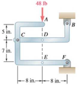
The 48-lb load is removed and a 288-lb · in. clockwise couple is applied successively at A, D, and E. Determine the components of the reactions at Band F if the couple is applied (a) at A, (b) at D, (c) at E.
(a)
The component of reactions at point B and F when the couple is applied at A.
Answer to Problem 6.89P
The x component of the reaction force at point B is
The x component of force applied is
Explanation of Solution
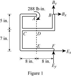
The free body diagram of the problem 6.89P is shown in figure 1 below.
A clockwise couple is applied at A,D, and E. Due to this couple, resultant reaction forces are experienced in points A, D, and E.
First consider the couple applied at point A.
Write the equation to find the sum of moments of force at point F.
Here,
Since the sum of moments of force at a point of a system in equilibrium is zero, rewrite the equation for the sum of moments.
Write the equation to find the x components of force.
Here,
Since the sum of forces at a point is zero in equilibrium, the above equation is rewritten.
Substitute
Write the equation to find the sum of y component of forces.
Here,
No force is applied in the y direction, therefore there will be no reaction also.
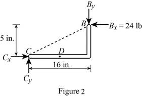
Consider figure 2.
Write the equation to find the y component of reaction force at point B.
Here,
Rewrite equation (I) to find the value of
Conclusion:
Observe figure 2.
Substitute
The y component of reaction force at point B is having a magnitude of
Substitute
The y component of the force applied at point b is
Therefore, the x component of the reaction force at point B is
The x component of force applied is
(b)
The component of reactions at point B and F when the couple is applied at D.
Answer to Problem 6.89P
The x component of the reaction force at point B is
The x component of force applied is
Explanation of Solution
The free body diagram of the problem 6.89P is shown in figure 1.
A clockwise couple is applied at A,D, and E. Due to this couple, resultant reaction forces are experienced in points A, D, and E.
Consider the couple applied at point D.
Write the equation to find the sum of moments of force at point F.
Here,
Since the sum of moments of force at a point of a system in equilibrium is zero, rewrite the equation for the sum of moments.
Write the equation to find the x components of force.
Here,
Since the sum of forces at a point is zero in equilibrium, the above equation is rewritten.
Substitute
Write the equation to find the sum of y component of forces.
Here,
No force is applied in the y direction, therefore there will be no reaction also.
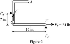
Consider figure 3.
Write the equation to find the y component of reaction force at point B.
Here,
Rewrite equation (I) to find the value of
Conclusion:
Observe figure 3.
Substitute
The y component of force at point B is having a magnitude of
Substitute
The y component of the reaction force applied at point B is
Therefore, the x component of the reaction force at point B is
The x component of force applied is
(c)
The component of reactions at point B and F when the couple is applied at E.
Answer to Problem 6.89P
The x component of the reaction force at point B is
The x component of force applied is
Explanation of Solution
The free body diagram of the problem 6.89P is shown in figure 1.
A clockwise couple is applied at A,D, and E. Due to this couple, resultant reaction forces are experienced in points A, D, and E.
First consider the couple applied at point E.
Write the equation to find the sum of moments of force at point F.
Here,
Since the sum of moments of force at a point of a system in equilibrium is zero, rewrite the equation for the sum of moments.
Write the equation to find the x components of force.
Here,
Since the sum of forces at a point is zero in equilibrium, the above equation is rewritten.
Substitute
Write the equation to find the sum of y component of forces.
Here,
No force is applied in the y direction, therefore there will be no reaction also.
Consider figure 4.
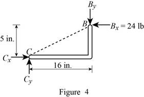
Write the equation to find the y component of reaction force at point B.
Here,
Rewrite equation (VII) to find the value of
Conclusion:
Observe figure 4.
Substitute
The y component of reaction force at point B is having a magnitude of
Substitute
The y component of the force applied at point b is
Therefore, the x component of the reaction force at point B is
The x component of force applied is
Want to see more full solutions like this?
Chapter 6 Solutions
Vector Mechanics for Engineers: Statics and Dynamics


- 7. In the following problems check to see if the set S is a vector subspace of the corresponding R. If it is not, explain why not. If it is, then find a basis and the dimension. (a) S = (b) S = {[],+,"} X1 x12x2 = x3 CR³ {[1], 4+4 = 1} CR³ X2arrow_forwardAAA Show laplace transform on 1; (+) to L (y(+)) : SY(s) = x (0) Y(s) = £ [lx (+)] = 5 x(+) · est de 2 -St L [ y (^) ] = So KG) et de D 2 D D AA Y(A) → Y(s) Ŷ (+) → s Y(s) -yarrow_forward1) In each of the following scenarios, based on the plane of impact (shown with an (n, t)) and the motion of mass 1, draw the direction of motion of mass 2 after the impact. Note that in all scenarios, mass 2 is initially at rest. What can you say about the nature of the motion of mass 2 regardless of the scenario? m1 15 <+ m2 2) y "L χ m1 m2 m1 בז m2 Farrow_forward
- 8. In the following check to see if the set S is a vector subspace of the corresponding Rn. If it is not, explain why not. If it is, then find a basis and the dimension. X1 (a) S = X2 {[2], n ≤ n } c X1 X2 CR² X1 (b) S X2 = X3 X4 x1 + x2 x3 = 0arrow_forward2) Suppose that two unequal masses m₁ and m₂ are moving with initial velocities V₁ and V₂, respectively. The masses hit each other and have a coefficient of restitution e. After the impact, mass 1 and 2 head to their respective gaps at angles a and ẞ, respectively. Derive expressions for each of the angles in terms of the initial velocities and the coefficient of restitution. m1 m2 8 m1 ↑ บา m2 ñ Вarrow_forwardThe fallowing question is from a reeds book on applied heat i am studying. Although the answer is provided, im struggling to understand the whole answer and the formulas and the steps theyre using. Also where some ov the values such as Hg and Hf come from in part i for example. Please explain step per step in detail thanks In an NH, refrigerator, the ammonia leaves the evaporatorand enters the cornpressor as dry saturated vapour at 2.68 bar,it leaves the compressor and enters the condenser at 8.57 bar with50" of superheat. it is condensed at constant pressure and leavesthe condenser as saturated liquid. If the rate of flow of the refrigerantthrough the circuit is 0.45 kglmin calculate (i) the compressorpower, (ii) the heat rejected to the condenser cooling water in kJ/s,an (iii) the refrigerating effect in kJ/s. From tables page 12, NH,:2.68 bar, hg= 1430.58.57 bar, hf = 275.1 h supht 50" = 1597.2Mass flow of refrigerant--- - - 0.0075 kgls 60Enthalpy gain per kg of refrigerant in…arrow_forward
- state the formulas for calculating work done by gasarrow_forwardExercises Find the solution of the following Differential Equations 1) y" + y = 3x² 3) "+2y+3y=27x 5) y"+y=6sin(x) 7) y"+4y+4y = 18 cosh(x) 9) (4)-5y"+4y = 10 cos(x) 11) y"+y=x²+x 13) y"-2y+y=e* 15) y+2y"-y'-2y=1-4x³ 2) y"+2y' + y = x² 4) "+y=-30 sin(4x) 6) y"+4y+3y=sin(x)+2 cos(x) 8) y"-2y+2y= 2e* cos(x) 10) y+y-2y=3e* 12) y"-y=e* 14) y"+y+y=x+4x³ +12x² 16) y"-2y+2y=2e* cos(x)arrow_forwardThe state of stress at a point is σ = -4.00 kpsi, σy = 16.00 kpsi, σ = -14.00 kpsi, Try = 11.00 kpsi, Tyz = 8.000 kpsi, and T = -14.00 kpsi. Determine the principal stresses. The principal normal stress σ₁ is determined to be [ The principal normal stress σ2 is determined to be [ The principal normal stress σ3 is determined to be kpsi. kpsi. The principal shear stress 71/2 is determined to be [ The principal shear stress 7½ is determined to be [ The principal shear stress T₁/, is determined to be [ kpsi. kpsi. kpsi. kpsi.arrow_forward
- Repeat Problem 28, except using a shaft that is rotatingand transmitting a torque of 150 N * m from the left bearing to the middle of the shaft. Also, there is a profile keyseat at the middle under the load. (I want to understand this problem)arrow_forwardProb 2. The material distorts into the dashed position shown. Determine the average normal strains &x, Ey and the shear strain Yxy at A, and the average normal strain along line BE. 50 mm B 200 mm 15 mm 30 mm D ΕΙ 50 mm x A 150 mm Farrow_forwardProb 3. The triangular plate is fixed at its base, and its apex A is given a horizontal displacement of 5 mm. Determine the shear strain, Yxy, at A. Prob 4. The triangular plate is fixed at its base, and its apex A is given a horizontal displacement of 5 mm. Determine the average normal strain & along the x axis. Prob 5. The triangular plate is fixed at its base, and its apex A is given a horizontal displacement of 5 mm. Determine the average normal strain &x along the x' axis. x' 45° 800 mm 45° 45% 800 mm 5 mmarrow_forward
 International Edition---engineering Mechanics: St...Mechanical EngineeringISBN:9781305501607Author:Andrew Pytel And Jaan KiusalaasPublisher:CENGAGE L