
Concept explainers
Videos
The gears A and D are rigidly attached to horizontal shafts that are held by frictionless bearings. Determine (a) the couple M0 that must be applied to shaft DEF to maintain equilibrium, (b) the reactions at G and H.
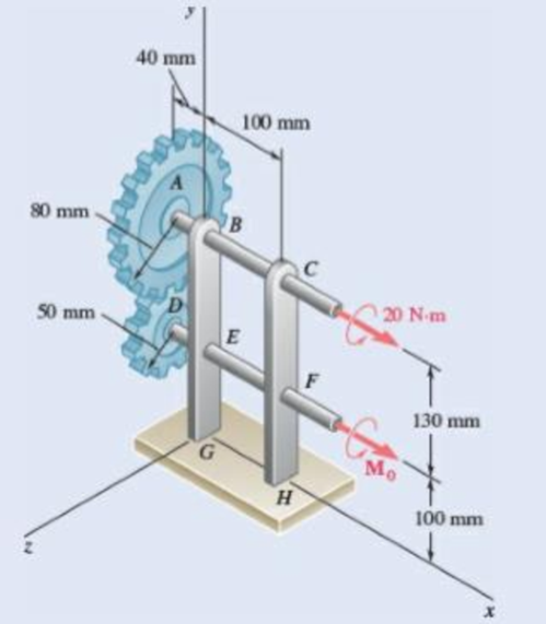
Fig. P6.159
(a)
The couple
Answer to Problem 6.159P
The couple
Explanation of Solution
Take all vectors along the
Radius of gear
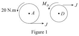
Consider the projection of the gears on
The free body diagram of the Gear
Here,
Write the expression for the moment at
Here,
Above equation implies that net moment at any point is the sum of product of each force acting on the system and perpendicular distance of the force and the point.
The moment at
Thus, write the complete expression of anticlockwise moment
Here,
At equilibrium, the sum of the moment acting at
Write the expression for the total anticlockwise moment acting at
Calculation:
Substitute
Substitute
Since the rotation is in the yz plane , the direction of couple is in
Therefore, the couple
(b)
The reaction at
Answer to Problem 6.159P
The point
Explanation of Solution
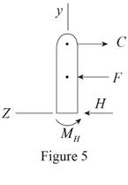
Free body diagram of Projection on
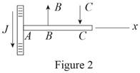
Here, is the tangential force acting on the gear,
From figure 2, write the equation of net moment about
Here,
Above equation implies that net moment at any point is the sum of product of each force acting on the system and perpendicular distance of the force and the point.
The moment at
Thus, write the complete expression of anticlockwise moment
Here,
At equilibrium, the sum of the moment acting at
Write the expression for the total anticlockwise moment acting at
Write the expression for the moment at
Here,
Above equation implies that net moment at any point is the sum of product of each force acting on the system and perpendicular distance of the force and the point.
At equilibrium, the sum of the moment acting at
Write the expression for the total anticlockwise moment acting at
Here,
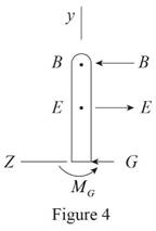
The free body diagram of the projection on
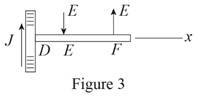
Here,
From figure 3, write the equation of net moment about
Here,
Above equation implies that net moment at any point is the sum of product of each force acting on the system and perpendicular distance of the force and the point.
The moment at
Thus, write the complete expression of anticlockwise moment
Here,
At equilibrium, the sum of the moment acting at
Write the expression for the total anticlockwise moment acting at
Write the expression for the moment at
Here,
Above equation implies that net moment at any point is the sum of product of each force acting on the system and perpendicular distance of the force and the point.
At equilibrium, the sum of the moment acting at
Write the expression for the total anticlockwise moment acting at
Here,
Consider the projection at
The free body diagram of the Bracket
Here,
Write the expression for the total force along
Since in this direction net force is equal to zero. Equate above equation to zero.
Since total moment of force about
Write the equilibrium moment of force about
The free body diagram of the Bracket
Here,
Write the expression for the total force along
Since in this direction net force is equal to zero. Equate above equation to zero.
Since total moment of force about
Write the equilibrium moment of force about
Calculation:
Substitute
Substitute
Substitute
Substitute
Substitute
Substitute
The negative sign indicate that it is directed along
Substitute
Substitute
The positive value indicate that it is directed along
Substitute
Therefore, the net force at
Want to see more full solutions like this?
Chapter 6 Solutions
Vector Mechanics for Engineers: Statics and Dynamics


- Research and select different values for the R ratio from various engine models, then analyze how these changes affect instantaneous velocity and acceleration, presenting your findings visually using graphs.arrow_forwardQu. 7 The v -t graph of a car while travelling along a road is shown. Draw the s -t and a -t graphs for the motion. I need to draw a graph and I need to show all work step by step please do not get short cut from dtnaarrow_forwardAn unpressurized cylindrical tank with a 100-foot diameter holds a 40-foot column of water. What is total force acting against the bottom of the tank?arrow_forward
- 7. In the following problems check to see if the set S is a vector subspace of the corresponding R. If it is not, explain why not. If it is, then find a basis and the dimension. (a) S = (b) S = {[],+,"} X1 x12x2 = x3 CR³ {[1], 4+4 = 1} CR³ X2arrow_forwardAAA Show laplace transform on 1; (+) to L (y(+)) : SY(s) = x (0) Y(s) = £ [lx (+)] = 5 x(+) · est de 2 -St L [ y (^) ] = So KG) et de D 2 D D AA Y(A) → Y(s) Ŷ (+) → s Y(s) -yarrow_forward1) In each of the following scenarios, based on the plane of impact (shown with an (n, t)) and the motion of mass 1, draw the direction of motion of mass 2 after the impact. Note that in all scenarios, mass 2 is initially at rest. What can you say about the nature of the motion of mass 2 regardless of the scenario? m1 15 <+ m2 2) y "L χ m1 m2 m1 בז m2 Farrow_forward
- 8. In the following check to see if the set S is a vector subspace of the corresponding Rn. If it is not, explain why not. If it is, then find a basis and the dimension. X1 (a) S = X2 {[2], n ≤ n } c X1 X2 CR² X1 (b) S X2 = X3 X4 x1 + x2 x3 = 0arrow_forward2) Suppose that two unequal masses m₁ and m₂ are moving with initial velocities V₁ and V₂, respectively. The masses hit each other and have a coefficient of restitution e. After the impact, mass 1 and 2 head to their respective gaps at angles a and ẞ, respectively. Derive expressions for each of the angles in terms of the initial velocities and the coefficient of restitution. m1 m2 8 m1 ↑ บา m2 ñ Вarrow_forwardThe fallowing question is from a reeds book on applied heat i am studying. Although the answer is provided, im struggling to understand the whole answer and the formulas and the steps theyre using. Also where some ov the values such as Hg and Hf come from in part i for example. Please explain step per step in detail thanks In an NH, refrigerator, the ammonia leaves the evaporatorand enters the cornpressor as dry saturated vapour at 2.68 bar,it leaves the compressor and enters the condenser at 8.57 bar with50" of superheat. it is condensed at constant pressure and leavesthe condenser as saturated liquid. If the rate of flow of the refrigerantthrough the circuit is 0.45 kglmin calculate (i) the compressorpower, (ii) the heat rejected to the condenser cooling water in kJ/s,an (iii) the refrigerating effect in kJ/s. From tables page 12, NH,:2.68 bar, hg= 1430.58.57 bar, hf = 275.1 h supht 50" = 1597.2Mass flow of refrigerant--- - - 0.0075 kgls 60Enthalpy gain per kg of refrigerant in…arrow_forward
- state the formulas for calculating work done by gasarrow_forwardExercises Find the solution of the following Differential Equations 1) y" + y = 3x² 3) "+2y+3y=27x 5) y"+y=6sin(x) 7) y"+4y+4y = 18 cosh(x) 9) (4)-5y"+4y = 10 cos(x) 11) y"+y=x²+x 13) y"-2y+y=e* 15) y+2y"-y'-2y=1-4x³ 2) y"+2y' + y = x² 4) "+y=-30 sin(4x) 6) y"+4y+3y=sin(x)+2 cos(x) 8) y"-2y+2y= 2e* cos(x) 10) y+y-2y=3e* 12) y"-y=e* 14) y"+y+y=x+4x³ +12x² 16) y"-2y+2y=2e* cos(x)arrow_forwardThe state of stress at a point is σ = -4.00 kpsi, σy = 16.00 kpsi, σ = -14.00 kpsi, Try = 11.00 kpsi, Tyz = 8.000 kpsi, and T = -14.00 kpsi. Determine the principal stresses. The principal normal stress σ₁ is determined to be [ The principal normal stress σ2 is determined to be [ The principal normal stress σ3 is determined to be kpsi. kpsi. The principal shear stress 71/2 is determined to be [ The principal shear stress 7½ is determined to be [ The principal shear stress T₁/, is determined to be [ kpsi. kpsi. kpsi. kpsi.arrow_forward
 Elements Of ElectromagneticsMechanical EngineeringISBN:9780190698614Author:Sadiku, Matthew N. O.Publisher:Oxford University Press
 Mechanics of Materials (10th Edition)Mechanical EngineeringISBN:9780134319650Author:Russell C. HibbelerPublisher:PEARSON
 Thermodynamics: An Engineering ApproachMechanical EngineeringISBN:9781259822674Author:Yunus A. Cengel Dr., Michael A. BolesPublisher:McGraw-Hill Education
 Control Systems EngineeringMechanical EngineeringISBN:9781118170519Author:Norman S. NisePublisher:WILEY
 Mechanics of Materials (MindTap Course List)Mechanical EngineeringISBN:9781337093347Author:Barry J. Goodno, James M. GerePublisher:Cengage Learning
 Engineering Mechanics: StaticsMechanical EngineeringISBN:9781118807330Author:James L. Meriam, L. G. Kraige, J. N. BoltonPublisher:WILEY