
Mechanics of Materials (10th Edition)
10th Edition
ISBN: 9780134319650
Author: Russell C. Hibbeler
Publisher: PEARSON
expand_more
expand_more
format_list_bulleted
Concept explainers
Videos
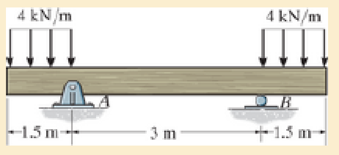
Textbook Question
Chapter 6.2, Problem 6.5FP
In each case, draw the shear and moment diagrams for the beam.
F6–5.
Expert Solution & Answer

Trending nowThis is a popular solution!

Students have asked these similar questions
Question 6
What kind of problem would arise if components of the strain tensor were defined
as v
please show steps, thanks
You design a pin joint. The pin is made of a material with the yield strength of 325
MPa and ultimate strength of 500 MPa. The maximum allowed stress in service is
expressed as a tensor
0
100 0
σ
100
0
0 MPa
0
0
Evaluate the safety factor SF for stress in this design.
Write answer unitless rounding to 2 decimal places and enter decimals even if those
are zeros.
Chapter 6 Solutions
Mechanics of Materials (10th Edition)
Ch. 6.2 - In each case, the beam is subjected to the...Ch. 6.2 - and then draw the shear and moment diagrams for...Ch. 6.2 - In each case, express the shear and moment...Ch. 6.2 - In each case, express the shear and moment...Ch. 6.2 - In each case, express the shear and moment...Ch. 6.2 - In each case, draw the shear and moment diagrams...Ch. 6.2 - In each case, draw the shear and moment diagrams...Ch. 6.2 - In each case, draw the shear and moment diagrams...Ch. 6.2 - In each case, draw the shear and moment diagrams...Ch. 6.2 - Draw the shear and moment diagrams for the shaft...
Ch. 6.2 - Draw the shear and moment diagrams for the beam,...Ch. 6.2 - Draw the shear and moment diagrams for the beam,...Ch. 6.2 - Express the shear and moment in terms of x for 0 ...Ch. 6.2 - Express the internal shear and moment in the...Ch. 6.2 - Draw the shear and moment diagrams for the shaft....Ch. 6.2 - Express the internal shear and moment in terms of...Ch. 6.2 - Draw the shear and moment diagrams for the beam,...Ch. 6.2 - If the force applied to the handle of the load...Ch. 6.2 - Draw the shear and moment diagrams for the shaft....Ch. 6.2 - The crane is used to support the engine, which has...Ch. 6.2 - Draw the shear and moment diagrams for the beam....Ch. 6.2 - Draw the shear and moment diagrams for the beam....Ch. 6.2 - Draw the shear and moment diagrams for the beam....Ch. 6.2 - Members ABC and BD of the counter chair are...Ch. 6.2 - A reinforced concrete pier is used to support the...Ch. 6.2 - Draw the shear and moment diagrams for the beam...Ch. 6.2 - The industrial robot is held in the stationary...Ch. 6.2 - Determine the placement distance a of the roller...Ch. 6.2 - Draw the shear and moment diagrams for the beam....Ch. 6.2 - Draw the shear and moment diagrams for the beam....Ch. 6.2 - Draw the shear and moment diagrams for the...Ch. 6.2 - The 150-lb man sits in the center of the boat,...Ch. 6.2 - Draw the shear and moment diagrams for the beam....Ch. 6.2 - The footing supports the load transmitted by the...Ch. 6.2 - Draw the shear and moment diagrams for the beam....Ch. 6.2 - Draw the shear and moment diagrams for the beam....Ch. 6.2 - Draw the shear and moment diagrams for the beam....Ch. 6.2 - Draw the shear and moment diagrams for the beam....Ch. 6.2 - Draw the shear and moment diagrams for the beam....Ch. 6.2 - The support at A allows the beam to slide freely...Ch. 6.2 - The smooth pin is supported by two leaves A and B...Ch. 6.2 - The shaft is supported by a smooth thrust bearing...Ch. 6.2 - Draw the shear and moment diagrams for the...Ch. 6.2 - Draw the shear and moment diagrams for the beam....Ch. 6.2 - Draw the shear and moment diagrams for the rod....Ch. 6.2 - Draw the shear and moment diagrams for the beam...Ch. 6.2 - The beam is used to support a uniform load along...Ch. 6.2 - Draw the shear and moment diagrams for the double...Ch. 6.2 - Draw the shear and moment diagrams for the simply...Ch. 6.2 - The compound beam is fixed at A, pin connected at...Ch. 6.2 - Draw the shear and moment diagrams for the...Ch. 6.2 - The compound beam is fixed at A, pin connected at...Ch. 6.2 - Draw the shear and moment diagrams for the beam....Ch. 6.2 - A short link at B is used to connect beams AB and...Ch. 6.2 - The truck is to be used to transport the concrete...Ch. 6.4 - Determine the moment of inertia of the cross...Ch. 6.4 - Determine the location of the centroid, y, and the...Ch. 6.4 - In each case, show how the bending stress acts on...Ch. 6.4 - Sketch the bending stress distribution over each...Ch. 6.4 - If the beam is subjected to a bending moment of M...Ch. 6.4 - If the beam is subjected to a bending moment of M...Ch. 6.4 - If the beam is subjected to a bending moment of M...Ch. 6.4 - If the beam is subjected to a bending moment of M...Ch. 6.4 - If the beam is subjected to a bending moment of M...Ch. 6.4 - An A-36 steel strip has an allowable bending...Ch. 6.4 - Determine the moment M that will produce a maximum...Ch. 6.4 - Determine the maximum tensile and compressive...Ch. 6.4 - The beam is constructed from four pieces of wood,...Ch. 6.4 - The beam is constructed from four pieces of wood,...Ch. 6.4 - The beam is made from three boards nailed together...Ch. 6.4 - The beam is made from three boards nailed together...Ch. 6.4 - If the built-up beam is subjected to an internal...Ch. 6.4 - If the built-up beam is subjected to an internal...Ch. 6.4 - The beam is subjected to a moment of M = 40 kN m....Ch. 6.4 - The steel shaft has a diameter of 2 in. It is...Ch. 6.4 - The beam is made of steel that has an allowable...Ch. 6.4 - A shaft is made of a polymer having an elliptical...Ch. 6.4 - Solve Prob. 6-65 if the moment M = 50 N m is...Ch. 6.4 - Prob. 6.67PCh. 6.4 - The shaft is supported by smooth journal bearings...Ch. 6.4 - The axle of the freight car is subjected to a...Ch. 6.4 - The strut on the utility pole supports the cable...Ch. 6.4 - The boat has a weight of 2300 lb and a center of...Ch. 6.4 - Determine the absolute maximum bending stress in...Ch. 6.4 - Determine the smallest allowable diameter of the...Ch. 6.4 - The pin is used to connect the three links...Ch. 6.4 - The shaft is supported by a thrust bearing at A...Ch. 6.4 - A timber beam has a cross section which is...Ch. 6.4 - If the beam is subjected to an internal moment of...Ch. 6.4 - If the allowable tensile and compressive stress...Ch. 6.4 - If the beam is subjected to an internal moment of...Ch. 6.4 - If the beam is subjected to a moment of M = 100 kN...Ch. 6.4 - If the beam is made of material having an...Ch. 6.4 - The shaft is supported by a smooth thrust bearing...Ch. 6.4 - The shaft is supported by a thrust bearing at A...Ch. 6.4 - If the intensity of the load w = 15 kN/m,...Ch. 6.4 - If the allowable bending stress is allow = 150...Ch. 6.4 - The beam is subjected to the triangular...Ch. 6.4 - The beam has a rectangular cross section with b =...Ch. 6.4 - Prob. 6.88PCh. 6.4 - If the compound beam in Prob. 642 has a square...Ch. 6.4 - If the beam in Prob. 628 has a rectangular cross...Ch. 6.4 - Determine the absolute maximum bending stress in...Ch. 6.4 - Determine, to the nearest millimeter, the smallest...Ch. 6.4 - Determine the absolute maximum bending stress in...Ch. 6.4 - Determine the absolute maximum bending stress in...Ch. 6.4 - Determine the smallest diameter of the shaft to...Ch. 6.4 - A log that is 2 ft in diameter is to be cut into a...Ch. 6.4 - A log that is 2 ft in diameter is to be cut into a...Ch. 6.4 - If the beam in Prob.63 has a rectangular cross...Ch. 6.4 - The simply supported truss is subjected to the...Ch. 6.4 - If d = 450 mm, determine the absolute maximum...Ch. 6.4 - If the allowable bending stress is allow = 6 MPa,...Ch. 6.4 - The beam has a rectangular cross section as shown....Ch. 6.4 - The beam has the rectangular cross section shown....Ch. 6.5 - Determine the bending stress at corners A and B....Ch. 6.5 - Determine the maximum bending stress in the beams...Ch. 6.5 - The member has a square cross section and is...Ch. 6.5 - The member has a square cross section and is...Ch. 6.5 - Consider the general case of a prismatic beam...Ch. 6.5 - Determine the bending stress at point A of the...Ch. 6.5 - Determine the bending stress at point A of the...Ch. 6.5 - The steel shaft is subjected to the two loads. If...Ch. 6.5 - The 65-mm-diameter steel shaft is subjected to the...Ch. 6.5 - For the section, lz = 31.7(10-5) m4, lY =...Ch. 6.5 - For the section, lz, = 31.7(10-5) m4, lY =...Ch. 6.5 - The box beam is subjected to a moment of M = 15...Ch. 6.5 - Determine the maximum magnitude of the bending...Ch. 6.5 - The shaft is subjected to the vertical and...Ch. 6.5 - For the section, Iy' = 31.7(10-6) m4, Iz' =...Ch. 6.5 - For the section, Iy' = 31.7(10-6) m4, Iz' =...Ch. 6.5 - If the applied distributed loading of w = 4 kN/m...Ch. 6.5 - Determine the maximum allowable intensity w of the...Ch. 6.9 - The composite beam is made of steel (A) bonded to...Ch. 6.9 - The composite beam is made of steel (A) bonded to...Ch. 6.9 - Segment A of the composite beam is made from...Ch. 6.9 - Segment A of the composite beam is made from...Ch. 6.9 - The white spruce beam is reinforced with A-992...Ch. 6.9 - The wooden section of the beam is reinforced with...Ch. 6.9 - The wooden section of the beam is reinforced with...Ch. 6.9 - The Douglas Fir beam is reinforced with A-992...Ch. 6.9 - The steel channel is used to reinforce the wood...Ch. 6.9 - A wood beam is reinforced with steel straps at its...Ch. 6.9 - A bimetallic strip is made from pieces of 2014-T6...Ch. 6.9 - Determine the maximum uniform distributed load w0...Ch. 6.9 - The composite beam is made of A-36 steel (A)...Ch. 6.9 - The composite beam is made of A-36 steel (A)...Ch. 6.9 - If the beam is subjected to a moment of M = 45 kN...Ch. 6.9 - The Douglas Fir beam is reinforced with A-36 steel...Ch. 6.9 - For the curved beam in Fig. 640a, show that when...Ch. 6.9 - The curved member is subjected to the moment of M...Ch. 6.9 - The curved member is made from material having an...Ch. 6.9 - The curved beam is subjected to a moment of M = 40...Ch. 6.9 - The curved beam is made from material having an...Ch. 6.9 - If P = 3 kN, determine the bending stress at...Ch. 6.9 - If the maximum bending stress at section a-a is...Ch. 6.9 - The elbow of the pipe has an outer radius of 0.75...Ch. 6.9 - If the bar is subjected to a couple as shown,...Ch. 6.9 - The curved bar used on a machine has a rectangular...Ch. 6.9 - The steel rod has a circular cross section. If it...Ch. 6.9 - If it is subjected to a moment of M = 5 kN m,...Ch. 6.9 - The member has a circular cross section. If the...Ch. 6.9 - The curved bar used on a machine has a rectangular...Ch. 6.9 - The bar is subjected to a moment of M = 100 N, m....Ch. 6.9 - The allowable bending stress for the bar is allow...Ch. 6.9 - The bar has a thickness of 1 in. and the allowable...Ch. 6.9 - The bar has a thickness of 1 in. and is subjected...Ch. 6.9 - The bar has a thickness of 0.5 in. and the...Ch. 6.9 - If the radius of each notch on the plate is r = 10...Ch. 6.9 - The stepped bar has a thickness of 10 mm....Ch. 6.9 - The bar has a thickness of 0.5 in. and is...Ch. 6.10 - Determine the shape factor for the wide-flange...Ch. 6.10 - The wide-flange member is made from an elastic...Ch. 6.10 - The rod has a circular cross section. If it is...Ch. 6.10 - The rod has a circular cross section. If it is...Ch. 6.10 - The beam is made of an elastic perfectly plastic...Ch. 6.10 - Determine the plastic moment Mp that can be...Ch. 6.10 - Determine the shape factor for the beam. Prob....Ch. 6.10 - The beam is made of elastic perfectly plastic...Ch. 6.10 - Determine the shape factor for the beam. Prob....Ch. 6.10 - The beam is made of an elastic perfectly plastic...Ch. 6.10 - Prob. 6.168PCh. 6.10 - Prob. 6.169PCh. 6.10 - Prob. 6.170PCh. 6.10 - The rod has a circular cross section. If it is...Ch. 6.10 - Determine the shape factor of the cross section....Ch. 6.10 - The beam is made of elastic perfectly plastic...Ch. 6.10 - Determine the shape factor for the member having...Ch. 6.10 - Determine the shape factor of the cross section....Ch. 6.10 - The box beam is made of an elastic perfectly...Ch. 6.10 - The beam is made of an elastic perfectly plastic...Ch. 6.10 - The plexiglass bar has a stress-strain curve that...Ch. 6.10 - The stress-strain diagram for a titanium alloy can...Ch. 6.10 - A beam is made from polypropylene plastic and has...Ch. 6.10 - The bar is made of an aluminum alloy having a...Ch. 6.10 - The beam is made of phenolic, a structural...Ch. 6 - Using appropriate measurements and data, explain...Ch. 6 - Determine the shape factor for the wide-flange...Ch. 6 - The compound beam consists of two segments that...Ch. 6 - The composite beam consists of a wood core and two...Ch. 6 - If it resists a moment of M = 125 N m, determine...Ch. 6 - Determine the maximum bending stress in the handle...Ch. 6 - The curved beam is subjected to a bending moment...Ch. 6 - Determine the shear and moment in the beam as...Ch. 6 - A wooden beam has a square cross section as shown...Ch. 6 - Draw the shear and moment diagrams for the shaft...Ch. 6 - The strut has a square cross section a by a and is...
Knowledge Booster


Learn more about
Need a deep-dive on the concept behind this application? Look no further. Learn more about this topic, mechanical-engineering and related others by exploring similar questions and additional content below.Similar questions
- 2. A single crystal of aluminum is oriented for a tensile test such that its slip plane normal makes an angle of 28.1° with the tensile axis. Three possible slip directions make angles of 62.4°, 72.0°, and 81.1° with the same tensile axis. (a) Which of these three slip directions is most favored? (b) If plastic deformation begins at a tensile stress of σ x = 1.95 MPa (280 psi), determine the critical resolved shear stress for aluminium. (c) If this single crystalspecimen is loaded under the new stress state: σ x =1.2 MPa σ y = -0.8 MPa, and τ xy = 0.6 MPa, howmuch is the resolve the shear stress along the most favored slip direction?arrow_forwardPlease explain how to do each part and tell me if my drawing is correct. thank youarrow_forward4. Determine which of the following flow fields represent a possible incompressible flow? (a) u= x²+2y+z; v=x-2y+z;w= -2xy + y² + 2z a (b) V=U cose U coso 1 (9) [1-9] Usino |1 (4)] [+] V=-Usin 1+1arrow_forward
- 3. Determine the flow rate through the pipe line show in the figure in ft³/s, and determine the pressures at A and C, in psi. 5' B C 12° 20' D 6"d 2nd- Water Aarrow_forward5. A flow is field given by V = x²₁³+xy, and determine 3 ·y³j- (a) Whether this is a one, two- or three-dimensional flow (b) Whether it is a possible incompressible flow (c) Determine the acceleration of a fluid particle at the location (X,Y,Z)=(1,2,3) (d) Whether the flow is rotational or irrotational flow?arrow_forwardSolve this problem and show all of the workarrow_forward
- Solve this problem and show all of the workarrow_forwarddraw the pneumatic circuit to operate a double-acting cylinder with: 1. Extension: Any of two manual conditions plus cylinder fully retracted, → Extension has both meter-in and meter-out, 2. Retraction: one manual conditions plus cylinder fully extended, → Retraction is very fast using quick exhaust valve.arrow_forwardCorrect answer is written below. Detailed and complete solution with fbd only. I will upvote, thank you. Expert solution plsarrow_forward
- Correct answer is written below. Detailed and complete solution with fbd only. I will upvote, thank you.arrow_forwardCorrect answer is written below. Detailed and complete solution with fbd only. I will upvote, thank you.arrow_forwardCorrect answer is written below. Detailed and complete solution only with fbd. I will upvote, thank you.arrow_forward
arrow_back_ios
SEE MORE QUESTIONS
arrow_forward_ios
Recommended textbooks for you
 Mechanics of Materials (MindTap Course List)Mechanical EngineeringISBN:9781337093347Author:Barry J. Goodno, James M. GerePublisher:Cengage Learning
Mechanics of Materials (MindTap Course List)
Mechanical Engineering
ISBN:9781337093347
Author:Barry J. Goodno, James M. Gere
Publisher:Cengage Learning
Understanding Shear Force and Bending Moment Diagrams; Author: The Efficient Engineer;https://www.youtube.com/watch?v=C-FEVzI8oe8;License: Standard YouTube License, CC-BY
Bending Stress; Author: moodlemech;https://www.youtube.com/watch?v=9QIqewkE6xM;License: Standard Youtube License