
Mechanics of Materials (10th Edition)
10th Edition
ISBN: 9780134319650
Author: Russell C. Hibbeler
Publisher: PEARSON
expand_more
expand_more
format_list_bulleted
Concept explainers
Videos
Textbook Question
Chapter 6.2, Problem 6.24P
Draw the shear and moment diagrams for the beam.
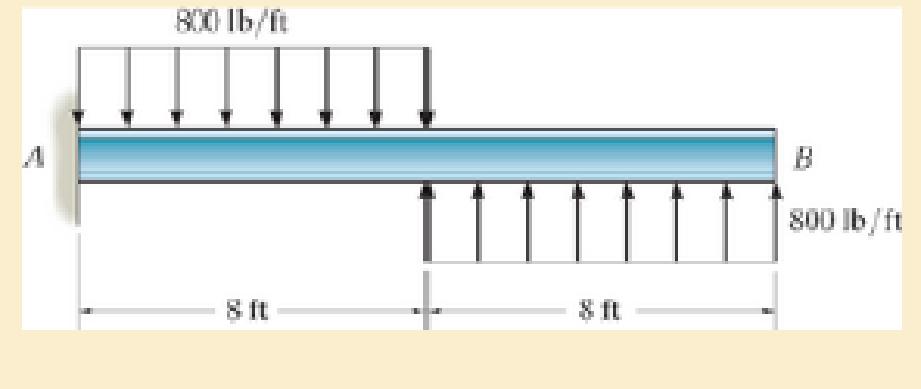
Prob. 6–24
Expert Solution & Answer
Want to see the full answer?
Check out a sample textbook solution
Students have asked these similar questions
Auto Controls
Using MATLAB , find the magnitude and phase plot of the compensators
NO COPIED SOLUTIONS
4-81 The corner shown in Figure P4-81 is initially uniform at 300°C and then suddenly
exposed to a convection environment at 50°C with h 60 W/m². °C. Assume the
=
2
solid has the properties of fireclay brick. Examine nodes 1, 2, 3, 4, and 5 and deter-
mine the maximum time increment which may be used for a transient numerical
calculation.
Figure P4-81
1
2
3
4
1 cm
5
6
1 cm
2 cm
h, T
+
2 cm
Auto Controls
A union feedback control system has the following open loop transfer function
where k>0 is a variable proportional gain
i. for K = 1 , derive the exact magnitude and phase expressions of G(jw).
ii) for K = 1 , identify the gaincross-over frequency (Wgc) [where IG(jo))| 1] and phase cross-overfrequency [where <G(jw) = - 180]. You can use MATLAB command "margin" to obtain there quantities.
iii) Calculate gain margin (in dB) and phase margin (in degrees) ·State whether the closed-loop is stable for K = 1 and briefly justify your answer based on the margin . (Gain marginPhase margin)
iv. what happens to the gain margin and Phase margin when you increase the value of K?you
You can use for loop in MATLAB to check that.Helpful matlab commands : if, bode, margin, rlocus
NO COPIED SOLUTIONS
Chapter 6 Solutions
Mechanics of Materials (10th Edition)
Ch. 6.2 - In each case, the beam is subjected to the...Ch. 6.2 - and then draw the shear and moment diagrams for...Ch. 6.2 - In each case, express the shear and moment...Ch. 6.2 - In each case, express the shear and moment...Ch. 6.2 - In each case, express the shear and moment...Ch. 6.2 - In each case, draw the shear and moment diagrams...Ch. 6.2 - In each case, draw the shear and moment diagrams...Ch. 6.2 - In each case, draw the shear and moment diagrams...Ch. 6.2 - In each case, draw the shear and moment diagrams...Ch. 6.2 - Draw the shear and moment diagrams for the shaft...
Ch. 6.2 - Draw the shear and moment diagrams for the beam,...Ch. 6.2 - Draw the shear and moment diagrams for the beam,...Ch. 6.2 - Express the shear and moment in terms of x for 0 ...Ch. 6.2 - Express the internal shear and moment in the...Ch. 6.2 - Draw the shear and moment diagrams for the shaft....Ch. 6.2 - Express the internal shear and moment in terms of...Ch. 6.2 - Draw the shear and moment diagrams for the beam,...Ch. 6.2 - If the force applied to the handle of the load...Ch. 6.2 - Draw the shear and moment diagrams for the shaft....Ch. 6.2 - The crane is used to support the engine, which has...Ch. 6.2 - Draw the shear and moment diagrams for the beam....Ch. 6.2 - Draw the shear and moment diagrams for the beam....Ch. 6.2 - Draw the shear and moment diagrams for the beam....Ch. 6.2 - Members ABC and BD of the counter chair are...Ch. 6.2 - A reinforced concrete pier is used to support the...Ch. 6.2 - Draw the shear and moment diagrams for the beam...Ch. 6.2 - The industrial robot is held in the stationary...Ch. 6.2 - Determine the placement distance a of the roller...Ch. 6.2 - Draw the shear and moment diagrams for the beam....Ch. 6.2 - Draw the shear and moment diagrams for the beam....Ch. 6.2 - Draw the shear and moment diagrams for the...Ch. 6.2 - The 150-lb man sits in the center of the boat,...Ch. 6.2 - Draw the shear and moment diagrams for the beam....Ch. 6.2 - The footing supports the load transmitted by the...Ch. 6.2 - Draw the shear and moment diagrams for the beam....Ch. 6.2 - Draw the shear and moment diagrams for the beam....Ch. 6.2 - Draw the shear and moment diagrams for the beam....Ch. 6.2 - Draw the shear and moment diagrams for the beam....Ch. 6.2 - Draw the shear and moment diagrams for the beam....Ch. 6.2 - The support at A allows the beam to slide freely...Ch. 6.2 - The smooth pin is supported by two leaves A and B...Ch. 6.2 - The shaft is supported by a smooth thrust bearing...Ch. 6.2 - Draw the shear and moment diagrams for the...Ch. 6.2 - Draw the shear and moment diagrams for the beam....Ch. 6.2 - Draw the shear and moment diagrams for the rod....Ch. 6.2 - Draw the shear and moment diagrams for the beam...Ch. 6.2 - The beam is used to support a uniform load along...Ch. 6.2 - Draw the shear and moment diagrams for the double...Ch. 6.2 - Draw the shear and moment diagrams for the simply...Ch. 6.2 - The compound beam is fixed at A, pin connected at...Ch. 6.2 - Draw the shear and moment diagrams for the...Ch. 6.2 - The compound beam is fixed at A, pin connected at...Ch. 6.2 - Draw the shear and moment diagrams for the beam....Ch. 6.2 - A short link at B is used to connect beams AB and...Ch. 6.2 - The truck is to be used to transport the concrete...Ch. 6.4 - Determine the moment of inertia of the cross...Ch. 6.4 - Determine the location of the centroid, y, and the...Ch. 6.4 - In each case, show how the bending stress acts on...Ch. 6.4 - Sketch the bending stress distribution over each...Ch. 6.4 - If the beam is subjected to a bending moment of M...Ch. 6.4 - If the beam is subjected to a bending moment of M...Ch. 6.4 - If the beam is subjected to a bending moment of M...Ch. 6.4 - If the beam is subjected to a bending moment of M...Ch. 6.4 - If the beam is subjected to a bending moment of M...Ch. 6.4 - An A-36 steel strip has an allowable bending...Ch. 6.4 - Determine the moment M that will produce a maximum...Ch. 6.4 - Determine the maximum tensile and compressive...Ch. 6.4 - The beam is constructed from four pieces of wood,...Ch. 6.4 - The beam is constructed from four pieces of wood,...Ch. 6.4 - The beam is made from three boards nailed together...Ch. 6.4 - The beam is made from three boards nailed together...Ch. 6.4 - If the built-up beam is subjected to an internal...Ch. 6.4 - If the built-up beam is subjected to an internal...Ch. 6.4 - The beam is subjected to a moment of M = 40 kN m....Ch. 6.4 - The steel shaft has a diameter of 2 in. It is...Ch. 6.4 - The beam is made of steel that has an allowable...Ch. 6.4 - A shaft is made of a polymer having an elliptical...Ch. 6.4 - Solve Prob. 6-65 if the moment M = 50 N m is...Ch. 6.4 - Prob. 6.67PCh. 6.4 - The shaft is supported by smooth journal bearings...Ch. 6.4 - The axle of the freight car is subjected to a...Ch. 6.4 - The strut on the utility pole supports the cable...Ch. 6.4 - The boat has a weight of 2300 lb and a center of...Ch. 6.4 - Determine the absolute maximum bending stress in...Ch. 6.4 - Determine the smallest allowable diameter of the...Ch. 6.4 - The pin is used to connect the three links...Ch. 6.4 - The shaft is supported by a thrust bearing at A...Ch. 6.4 - A timber beam has a cross section which is...Ch. 6.4 - If the beam is subjected to an internal moment of...Ch. 6.4 - If the allowable tensile and compressive stress...Ch. 6.4 - If the beam is subjected to an internal moment of...Ch. 6.4 - If the beam is subjected to a moment of M = 100 kN...Ch. 6.4 - If the beam is made of material having an...Ch. 6.4 - The shaft is supported by a smooth thrust bearing...Ch. 6.4 - The shaft is supported by a thrust bearing at A...Ch. 6.4 - If the intensity of the load w = 15 kN/m,...Ch. 6.4 - If the allowable bending stress is allow = 150...Ch. 6.4 - The beam is subjected to the triangular...Ch. 6.4 - The beam has a rectangular cross section with b =...Ch. 6.4 - Prob. 6.88PCh. 6.4 - If the compound beam in Prob. 642 has a square...Ch. 6.4 - If the beam in Prob. 628 has a rectangular cross...Ch. 6.4 - Determine the absolute maximum bending stress in...Ch. 6.4 - Determine, to the nearest millimeter, the smallest...Ch. 6.4 - Determine the absolute maximum bending stress in...Ch. 6.4 - Determine the absolute maximum bending stress in...Ch. 6.4 - Determine the smallest diameter of the shaft to...Ch. 6.4 - A log that is 2 ft in diameter is to be cut into a...Ch. 6.4 - A log that is 2 ft in diameter is to be cut into a...Ch. 6.4 - If the beam in Prob.63 has a rectangular cross...Ch. 6.4 - The simply supported truss is subjected to the...Ch. 6.4 - If d = 450 mm, determine the absolute maximum...Ch. 6.4 - If the allowable bending stress is allow = 6 MPa,...Ch. 6.4 - The beam has a rectangular cross section as shown....Ch. 6.4 - The beam has the rectangular cross section shown....Ch. 6.5 - Determine the bending stress at corners A and B....Ch. 6.5 - Determine the maximum bending stress in the beams...Ch. 6.5 - The member has a square cross section and is...Ch. 6.5 - The member has a square cross section and is...Ch. 6.5 - Consider the general case of a prismatic beam...Ch. 6.5 - Determine the bending stress at point A of the...Ch. 6.5 - Determine the bending stress at point A of the...Ch. 6.5 - The steel shaft is subjected to the two loads. If...Ch. 6.5 - The 65-mm-diameter steel shaft is subjected to the...Ch. 6.5 - For the section, lz = 31.7(10-5) m4, lY =...Ch. 6.5 - For the section, lz, = 31.7(10-5) m4, lY =...Ch. 6.5 - The box beam is subjected to a moment of M = 15...Ch. 6.5 - Determine the maximum magnitude of the bending...Ch. 6.5 - The shaft is subjected to the vertical and...Ch. 6.5 - For the section, Iy' = 31.7(10-6) m4, Iz' =...Ch. 6.5 - For the section, Iy' = 31.7(10-6) m4, Iz' =...Ch. 6.5 - If the applied distributed loading of w = 4 kN/m...Ch. 6.5 - Determine the maximum allowable intensity w of the...Ch. 6.9 - The composite beam is made of steel (A) bonded to...Ch. 6.9 - The composite beam is made of steel (A) bonded to...Ch. 6.9 - Segment A of the composite beam is made from...Ch. 6.9 - Segment A of the composite beam is made from...Ch. 6.9 - The white spruce beam is reinforced with A-992...Ch. 6.9 - The wooden section of the beam is reinforced with...Ch. 6.9 - The wooden section of the beam is reinforced with...Ch. 6.9 - The Douglas Fir beam is reinforced with A-992...Ch. 6.9 - The steel channel is used to reinforce the wood...Ch. 6.9 - A wood beam is reinforced with steel straps at its...Ch. 6.9 - A bimetallic strip is made from pieces of 2014-T6...Ch. 6.9 - Determine the maximum uniform distributed load w0...Ch. 6.9 - The composite beam is made of A-36 steel (A)...Ch. 6.9 - The composite beam is made of A-36 steel (A)...Ch. 6.9 - If the beam is subjected to a moment of M = 45 kN...Ch. 6.9 - The Douglas Fir beam is reinforced with A-36 steel...Ch. 6.9 - For the curved beam in Fig. 640a, show that when...Ch. 6.9 - The curved member is subjected to the moment of M...Ch. 6.9 - The curved member is made from material having an...Ch. 6.9 - The curved beam is subjected to a moment of M = 40...Ch. 6.9 - The curved beam is made from material having an...Ch. 6.9 - If P = 3 kN, determine the bending stress at...Ch. 6.9 - If the maximum bending stress at section a-a is...Ch. 6.9 - The elbow of the pipe has an outer radius of 0.75...Ch. 6.9 - If the bar is subjected to a couple as shown,...Ch. 6.9 - The curved bar used on a machine has a rectangular...Ch. 6.9 - The steel rod has a circular cross section. If it...Ch. 6.9 - If it is subjected to a moment of M = 5 kN m,...Ch. 6.9 - The member has a circular cross section. If the...Ch. 6.9 - The curved bar used on a machine has a rectangular...Ch. 6.9 - The bar is subjected to a moment of M = 100 N, m....Ch. 6.9 - The allowable bending stress for the bar is allow...Ch. 6.9 - The bar has a thickness of 1 in. and the allowable...Ch. 6.9 - The bar has a thickness of 1 in. and is subjected...Ch. 6.9 - The bar has a thickness of 0.5 in. and the...Ch. 6.9 - If the radius of each notch on the plate is r = 10...Ch. 6.9 - The stepped bar has a thickness of 10 mm....Ch. 6.9 - The bar has a thickness of 0.5 in. and is...Ch. 6.10 - Determine the shape factor for the wide-flange...Ch. 6.10 - The wide-flange member is made from an elastic...Ch. 6.10 - The rod has a circular cross section. If it is...Ch. 6.10 - The rod has a circular cross section. If it is...Ch. 6.10 - The beam is made of an elastic perfectly plastic...Ch. 6.10 - Determine the plastic moment Mp that can be...Ch. 6.10 - Determine the shape factor for the beam. Prob....Ch. 6.10 - The beam is made of elastic perfectly plastic...Ch. 6.10 - Determine the shape factor for the beam. Prob....Ch. 6.10 - The beam is made of an elastic perfectly plastic...Ch. 6.10 - Prob. 6.168PCh. 6.10 - Prob. 6.169PCh. 6.10 - Prob. 6.170PCh. 6.10 - The rod has a circular cross section. If it is...Ch. 6.10 - Determine the shape factor of the cross section....Ch. 6.10 - The beam is made of elastic perfectly plastic...Ch. 6.10 - Determine the shape factor for the member having...Ch. 6.10 - Determine the shape factor of the cross section....Ch. 6.10 - The box beam is made of an elastic perfectly...Ch. 6.10 - The beam is made of an elastic perfectly plastic...Ch. 6.10 - The plexiglass bar has a stress-strain curve that...Ch. 6.10 - The stress-strain diagram for a titanium alloy can...Ch. 6.10 - A beam is made from polypropylene plastic and has...Ch. 6.10 - The bar is made of an aluminum alloy having a...Ch. 6.10 - The beam is made of phenolic, a structural...Ch. 6 - Using appropriate measurements and data, explain...Ch. 6 - Determine the shape factor for the wide-flange...Ch. 6 - The compound beam consists of two segments that...Ch. 6 - The composite beam consists of a wood core and two...Ch. 6 - If it resists a moment of M = 125 N m, determine...Ch. 6 - Determine the maximum bending stress in the handle...Ch. 6 - The curved beam is subjected to a bending moment...Ch. 6 - Determine the shear and moment in the beam as...Ch. 6 - A wooden beam has a square cross section as shown...Ch. 6 - Draw the shear and moment diagrams for the shaft...Ch. 6 - The strut has a square cross section a by a and is...
Knowledge Booster


Learn more about
Need a deep-dive on the concept behind this application? Look no further. Learn more about this topic, mechanical-engineering and related others by exploring similar questions and additional content below.Similar questions
- Auto Controls Hand sketch the root Focus of the following transfer function How many asymptotes are there ?what are the angles of the asymptotes?Does the system remain stable for all values of K NO COPIED SOLUTIONSarrow_forward-400" 150" in Datum 80" 90" -280"arrow_forwardUsing hand drawing both of themarrow_forward
- A 10-kg box is pulled along P,Na rough surface by a force P, as shown in thefigure. The pulling force linearly increaseswith time, while the particle is motionless att = 0s untilit reaches a maximum force of100 Nattimet = 4s. If the ground has staticand kinetic friction coefficients of u, = 0.6 andHU, = 0.4 respectively, determine the velocityof the A 1 0 - kg box is pulled along P , N a rough surface by a force P , as shown in the figure. The pulling force linearly increases with time, while the particle is motionless at t = 0 s untilit reaches a maximum force of 1 0 0 Nattimet = 4 s . If the ground has static and kinetic friction coefficients of u , = 0 . 6 and HU , = 0 . 4 respectively, determine the velocity of the particle att = 4 s .arrow_forwardCalculate the speed of the driven member with the following conditions: Diameter of the motor pulley: 4 in Diameter of the driven pulley: 12 in Speed of the motor pulley: 1800 rpmarrow_forward4. In the figure, shaft A made of AISI 1010 hot-rolled steel, is welded to a fixed support and is subjected to loading by equal and opposite Forces F via shaft B. Stress concentration factors K₁ (1.7) and Kts (1.6) are induced by the 3mm fillet. Notch sensitivities are q₁=0.9 and qts=1. The length of shaft A from the fixed support to the connection at shaft B is 1m. The load F cycles from 0.5 to 2kN and a static load P is 100N. For shaft A, find the factor of safety (for infinite life) using the modified Goodman fatigue failure criterion. 3 mm fillet Shaft A 20 mm 25 mm Shaft B 25 mmarrow_forward
arrow_back_ios
SEE MORE QUESTIONS
arrow_forward_ios
Recommended textbooks for you
 Elements Of ElectromagneticsMechanical EngineeringISBN:9780190698614Author:Sadiku, Matthew N. O.Publisher:Oxford University Press
 Mechanics of Materials (10th Edition)Mechanical EngineeringISBN:9780134319650Author:Russell C. HibbelerPublisher:PEARSON
 Thermodynamics: An Engineering ApproachMechanical EngineeringISBN:9781259822674Author:Yunus A. Cengel Dr., Michael A. BolesPublisher:McGraw-Hill Education
 Control Systems EngineeringMechanical EngineeringISBN:9781118170519Author:Norman S. NisePublisher:WILEY
 Mechanics of Materials (MindTap Course List)Mechanical EngineeringISBN:9781337093347Author:Barry J. Goodno, James M. GerePublisher:Cengage Learning
 Engineering Mechanics: StaticsMechanical EngineeringISBN:9781118807330Author:James L. Meriam, L. G. Kraige, J. N. BoltonPublisher:WILEY
Elements Of Electromagnetics
Mechanical Engineering
ISBN:9780190698614
Author:Sadiku, Matthew N. O.
Publisher:Oxford University Press
Mechanics of Materials (10th Edition)
Mechanical Engineering
ISBN:9780134319650
Author:Russell C. Hibbeler
Publisher:PEARSON
Thermodynamics: An Engineering Approach
Mechanical Engineering
ISBN:9781259822674
Author:Yunus A. Cengel Dr., Michael A. Boles
Publisher:McGraw-Hill Education
Control Systems Engineering
Mechanical Engineering
ISBN:9781118170519
Author:Norman S. Nise
Publisher:WILEY
Mechanics of Materials (MindTap Course List)
Mechanical Engineering
ISBN:9781337093347
Author:Barry J. Goodno, James M. Gere
Publisher:Cengage Learning
Engineering Mechanics: Statics
Mechanical Engineering
ISBN:9781118807330
Author:James L. Meriam, L. G. Kraige, J. N. Bolton
Publisher:WILEY
Understanding Shear Force and Bending Moment Diagrams; Author: The Efficient Engineer;https://www.youtube.com/watch?v=C-FEVzI8oe8;License: Standard YouTube License, CC-BY
Bending Stress; Author: moodlemech;https://www.youtube.com/watch?v=9QIqewkE6xM;License: Standard Youtube License