
Tutorials in Introductory Physics
1st Edition
ISBN: 9780130970695
Author: Peter S. Shaffer, Lillian C. McDermott
Publisher: Addison Wesley
expand_more
expand_more
format_list_bulleted
Videos
Textbook Question
thumb_up100%
Chapter 6.2, Problem 2cT
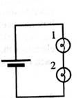
Predict what the voltmeter would read if it were connected to measure the potential difference across the network of bulb 1 and bulb 2 together. Explain.
Test your prediction.
How does the potential difference across the network of bulbs compare to the potential difference across the battery?
Expert Solution & Answer

Learn your wayIncludes step-by-step video

schedule01:54
Students have asked these similar questions
2. A battleship simultaneously fires two shells at enemy ships. If the shells follow the
parabolic trajectories shown, which ship gets hit first?
a. A
b. both at the same time
C.
B
d. need more information
battleship
B
A m₁ = 1.70-kg aluminum block and a m₂ = 8.00-kg copper block are connected by a light string over a frictionless pulley. The two blocks are allowed to move on a fixed steel block wedge (of angle 0 = 31.5°) as shown in the figure. (For aluminum on steel, μk
k = 0.36.)
Мк
Aluminum
m
Copper
= 0.47. For copper on steel,
Steel
m2
Ꮎ
(a) the acceleration of the two blocks
m/s²
(b) the tension in the string
N
While the 83.3 kg Dora Milaje is in equilibrium, the rope makes a 70.0˚ angle with the horizontal. Assuming the coefficient of friction between her shoes and the ship is 0.772 and her static friction is at its maximum value, what is the tension in the cable?
Chapter 6 Solutions
Tutorials in Introductory Physics
Ch. 6.1 - Obtain a battery, a light bulb, and a single piece...Ch. 6.1 - A student has briefly connected a wire across the...Ch. 6.1 - Light a bulb using a battery and a single wire....Ch. 6.1 - Carefully examine a bulb. Two wires extend from...Ch. 6.1 - Compare the brightness of the two bulb with each...Ch. 6.1 - Compare the brightness of each of the bulbs in the...Ch. 6.1 - We may think of a bulb as percentage an obstacle,...Ch. 6.1 - Compare the brightness of the bulbs in this...Ch. 6.1 - Is the brightness of each bulb in the two-bulb...Ch. 6.1 - Formulate a rule for predicting how the current...
Ch. 6.1 - Does the amount of current through a battery seem...Ch. 6.1 - Unscrew one of the bulbs in the two-bulb parallel...Ch. 6.1 - The circuit at tight contains three identical...Ch. 6.1 - Show that a simple application of the model for...Ch. 6.2 - The circuits at right contain identical batteries,...Ch. 6.2 - The circuits at right contain identical batteries...Ch. 6.2 - Predict the relative brightness of bulbs...Ch. 6.2 - Set up the circuit with a single bulb and the...Ch. 6.2 - Set up the circuit containing two bulbs in series...Ch. 6.2 - Predict what the voltmeter would read if it were...Ch. 6.2 - Set up the circuit with two bulbs in parallel as...Ch. 6.2 - Answer the following questions based on the...Ch. 6.2 - Set up the circuit with three bulbs as shown and...Ch. 6.2 - Before setting up the circuit shown at right:...Ch. 6.2 - Both circuits al right have more than one path for...Ch. 6.3 - A capacitor is connected to a battery, bulb, and...Ch. 6.3 - Remove the capacitor and the bulb from the...Ch. 6.3 - Suppose an uncharged capacitor is connected in...Ch. 6.3 - Suppose that instead of connecting the uncharged...Ch. 6.3 - Suppose that the bulbs were connected in parallel...Ch. 6.3 - After completing the experiments above, two...Ch. 6.3 - Suppose that a different capacitor of smaller...Ch. 6.3 - Before connecting the circuit a student makes the...Ch. 6.3 - Make the following prediction on the basis of your...
Additional Science Textbook Solutions
Find more solutions based on key concepts
In what way do the membranes of a eukaryotic cell vary? A. Phospholipids are found only in certain membranes. B...
Campbell Biology in Focus (2nd Edition)
14.19 In Genetic Analysis, we designed a screen to identify conditional mutants of S. cerevisiae in which the s...
Genetic Analysis: An Integrated Approach (3rd Edition)
WRITE ABOUT A THEME: ENERGY In a short essay (about 100150 words), discuss how prokaryotes and other members of...
Campbell Biology (11th Edition)
33. A copper wire is 1.0 mm in diameter and carries a current of 20 A. What is the electric field strength insi...
College Physics: A Strategic Approach (3rd Edition)
1.3 Obtain a bottle of multivitamins and read the list of ingredients. What are four chemicals from the list?
Chemistry: An Introduction to General, Organic, and Biological Chemistry (13th Edition)
Choose the best answer to each of the following. Explain your reasoning. An astronomical unit is (a) any planet...
Cosmic Perspective Fundamentals
Knowledge Booster


Learn more about
Need a deep-dive on the concept behind this application? Look no further. Learn more about this topic, physics and related others by exploring similar questions and additional content below.Similar questions
- Can someone help me asnwer this thank youarrow_forwardPlease solve and answer the problem correctly please. Be sure to give explanations on each step and write neatlyplease. Thank you!! ( preferably type the explantion, steps and solution please )arrow_forwardA square coil that has 17.5 cm on each side containing 17 loops lies flat on your desk as shown on this page. A uniform magnetic field of magnitude 4.60 × 10-ST points into this page. If a 8.50-A clockwise Current flows through the coil. ca) determine the torque on the coil. N.m (b) which edge of the coil rises up? choose one 。 Bottom отор and explain. O Right • None of these О Left.arrow_forward
- A circular loop of wire with a diameter of 13.0 cm is in the horizontal plane and carries of 1.70 A clockwise, as viewed from underneath. What is the magnitude magnetic field as the center of the loop? -T what is the direction of magnetic field at the center or down? please explain. of the loop? uparrow_forwardStarlord has a mass of 89.3 kg and Groot is pulling the bag with a force of 384. N at an angle of 35.0˚ as is shown in the figure below. What is the coefficient of kinetic friction if they are moving at a constant speed of 2.31 m/s?arrow_forwardEarly on in the video game Shadow of the Tomb Raider Lara Croft uses a winch to pull a heavy crate of stone up a 23.6° incline. If Lara causes the 66.0 kg crate to accelerate at 2.79 m/s2 up the ramp, what is the tension in the rope pulling the block? The coefficient of kinetic friction between the block and the ground is 0.503.arrow_forward
- A player kicks a football at the start of the game. After a 4 second flight, the ball touches the ground 50 m from the kicking tee. Assume air resistance is negligible and the take-off and landing height are the same (i.e., time to peak = time to fall = ½ total flight time). (Note: For each question draw a diagram to show the vector/s. Show all the step and provide units in the answers. Provide answer to 2 decimal places unless stated otherwise.) Calculate and answer all parts. Only use equations PROVIDED:arrow_forwardA shot putter releases a shot at 13 m/s at an angle of 42 degrees to the horizontal and from a height of 1.83 m above the ground. (Note: For each question draw a diagram to show the vector/s. Show all the step and provide units in the answers. Provide answer to 2 decimal places unless stated otherwise.) Calculate and answer all parts. Only use equations PROVIDED:arrow_forwardIf a person jumps upwards with a vertical velocity of 5 m/s, What is their velocity 0.5 second into the jump?arrow_forward
- A solid sphere 22 cm in radius carries 17 μC, distributed uniformly throughout its volume. Part A Find the electric field strength 12 cm from the sphere's center. Express your answer using two significant figures. E₁ = ΜΕ ΑΣΦ ха Хь b Submit Previous Answers Request Answer <☑ × Incorrect; Try Again; 4 attempts remaining ▾ Part B ? |X| X.10" <☑ Find the electric field strength 22 cm from the sphere's center. Express your answer using two significant figures. ΜΕ ΑΣΦ E2 = Submit Request Answer ▾ Part C ? MN/C Find the electric field strength 44 cm from the sphere's center. Express your answer using two significant figures. ΕΠΙ ΑΣΦ E3 = Submit Request Answer ? MN/C MN/Carrow_forwardNo chatgpt plsarrow_forwardIn a naval battle, a battleship is attempting to fire on a destroyer. The battleship is a distance d1 = 2,150 m to the east of the peak of a mountain on an island, as shown in the figure below. The destroyer is attempting to evade cannon shells fired from the battleship by hiding on the west side of the island. The initial speed of the shells that the battleship fires is vi = 245 m/s. The peak of the mountain is h = 1,840 m above sea level, and the western shore of the island is a horizontal distance d2 = 250 m from the peak. What are the distances (in m), as measured from the western shore of the island, at which the destroyer will be safe from fire from the battleship? (Note the figure is not to scale. You may assume that the height and width of the destroyer are small compared to d1 and h.)arrow_forward
arrow_back_ios
SEE MORE QUESTIONS
arrow_forward_ios
Recommended textbooks for you
 Glencoe Physics: Principles and Problems, Student...PhysicsISBN:9780078807213Author:Paul W. ZitzewitzPublisher:Glencoe/McGraw-Hill

 College PhysicsPhysicsISBN:9781938168000Author:Paul Peter Urone, Roger HinrichsPublisher:OpenStax College
 College PhysicsPhysicsISBN:9781305952300Author:Raymond A. Serway, Chris VuillePublisher:Cengage Learning
 Physics for Scientists and Engineers, Technology ...PhysicsISBN:9781305116399Author:Raymond A. Serway, John W. JewettPublisher:Cengage Learning
Glencoe Physics: Principles and Problems, Student...
Physics
ISBN:9780078807213
Author:Paul W. Zitzewitz
Publisher:Glencoe/McGraw-Hill
College Physics
Physics
ISBN:9781938168000
Author:Paul Peter Urone, Roger Hinrichs
Publisher:OpenStax College
College Physics
Physics
ISBN:9781305952300
Author:Raymond A. Serway, Chris Vuille
Publisher:Cengage Learning
Physics for Scientists and Engineers, Technology ...
Physics
ISBN:9781305116399
Author:Raymond A. Serway, John W. Jewett
Publisher:Cengage Learning
Series & Parallel - Potential Divider Circuits - GCSE & A-level Physics; Author: Science Shorts;https://www.youtube.com/watch?v=vf8HVTVvsdw;License: Standard YouTube License, CC-BY