
Tutorials in Introductory Physics
1st Edition
ISBN: 9780130970695
Author: Peter S. Shaffer, Lillian C. McDermott
Publisher: Addison Wesley
expand_more
expand_more
format_list_bulleted
Videos
Textbook Question
thumb_up100%
Chapter 6.3, Problem 2cT
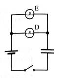
1. Predict how the initial brightness of bulb D compares to the initial brightness of bulb li. Explain.
2. Predict how the initial brightness of bulb 1) compares to the initial brightness of bulbs A, B, and C above. Explain.
3. Predict how the final charge on the capacitor compares to the final charge on the capacitor from part A. Explain.
Set up the circuit and check your predictions. If your prediction is in conflict with your observation, how can you account for your observation?
Expert Solution & Answer

Learn your wayIncludes step-by-step video

schedule07:48
Students have asked these similar questions
Hi,
I have canceled, why did you charge me again?
No chatgpt pls will upvote
No chatgpt pls will upvote
Chapter 6 Solutions
Tutorials in Introductory Physics
Ch. 6.1 - Obtain a battery, a light bulb, and a single piece...Ch. 6.1 - A student has briefly connected a wire across the...Ch. 6.1 - Light a bulb using a battery and a single wire....Ch. 6.1 - Carefully examine a bulb. Two wires extend from...Ch. 6.1 - Compare the brightness of the two bulb with each...Ch. 6.1 - Compare the brightness of each of the bulbs in the...Ch. 6.1 - We may think of a bulb as percentage an obstacle,...Ch. 6.1 - Compare the brightness of the bulbs in this...Ch. 6.1 - Is the brightness of each bulb in the two-bulb...Ch. 6.1 - Formulate a rule for predicting how the current...
Ch. 6.1 - Does the amount of current through a battery seem...Ch. 6.1 - Unscrew one of the bulbs in the two-bulb parallel...Ch. 6.1 - The circuit at tight contains three identical...Ch. 6.1 - Show that a simple application of the model for...Ch. 6.2 - The circuits at right contain identical batteries,...Ch. 6.2 - The circuits at right contain identical batteries...Ch. 6.2 - Predict the relative brightness of bulbs...Ch. 6.2 - Set up the circuit with a single bulb and the...Ch. 6.2 - Set up the circuit containing two bulbs in series...Ch. 6.2 - Predict what the voltmeter would read if it were...Ch. 6.2 - Set up the circuit with two bulbs in parallel as...Ch. 6.2 - Answer the following questions based on the...Ch. 6.2 - Set up the circuit with three bulbs as shown and...Ch. 6.2 - Before setting up the circuit shown at right:...Ch. 6.2 - Both circuits al right have more than one path for...Ch. 6.3 - A capacitor is connected to a battery, bulb, and...Ch. 6.3 - Remove the capacitor and the bulb from the...Ch. 6.3 - Suppose an uncharged capacitor is connected in...Ch. 6.3 - Suppose that instead of connecting the uncharged...Ch. 6.3 - Suppose that the bulbs were connected in parallel...Ch. 6.3 - After completing the experiments above, two...Ch. 6.3 - Suppose that a different capacitor of smaller...Ch. 6.3 - Before connecting the circuit a student makes the...Ch. 6.3 - Make the following prediction on the basis of your...
Additional Science Textbook Solutions
Find more solutions based on key concepts
In your own words, briefly distinguish between relative dates and numerical dates.
Applications and Investigations in Earth Science (9th Edition)
Two culture media were inoculated with four different bacteria. After incubation, the following results were ob...
Microbiology: An Introduction
Level 2: Application/Analysis 4. Nitrifying bactcria participatc in the nitrogen cycle mainly by (A) converting...
Campbell Biology (11th Edition)
15. A good scientific hypothesis is based on existing evidence and leads to testable predictions. What hypothes...
Campbell Biology: Concepts & Connections (9th Edition)
For the generic equilibrium HA(aq) ⇌ H + (aq) + A- (aq), which of these statements is true?
The equilibrium con...
Chemistry: The Central Science (14th Edition)
The bioremediation process shown in the photograph is used to remove benzene and other hydrocarbons from soil c...
Microbiology: An Introduction
Knowledge Booster


Learn more about
Need a deep-dive on the concept behind this application? Look no further. Learn more about this topic, physics and related others by exploring similar questions and additional content below.Similar questions
- No chatgpt pls will upvotearrow_forwardYou are standing a distance x = 1.75 m away from this mirror. The object you are looking at is y = 0.29 m from the mirror. The angle of incidence is θ = 30°. What is the exact distance from you to the image?arrow_forwardFor each of the actions depicted below, a magnet and/or metal loop moves with velocity v→ (v→ is constant and has the same magnitude in all parts). Determine whether a current is induced in the metal loop. If so, indicate the direction of the current in the loop, either clockwise or counterclockwise when seen from the right of the loop. The axis of the magnet is lined up with the center of the loop. For the action depicted in (Figure 5), indicate the direction of the induced current in the loop (clockwise, counterclockwise or zero, when seen from the right of the loop). I know that the current is clockwise, I just dont understand why. Please fully explain why it's clockwise, Thank youarrow_forward
- A planar double pendulum consists of two point masses \[m_1 = 1.00~\mathrm{kg}, \qquad m_2 = 1.00~\mathrm{kg}\]connected by massless, rigid rods of lengths \[L_1 = 1.00~\mathrm{m}, \qquad L_2 = 1.20~\mathrm{m}.\]The upper rod is hinged to a fixed pivot; gravity acts vertically downward with\[g = 9.81~\mathrm{m\,s^{-2}}.\]Define the generalized coordinates \(\theta_1,\theta_2\) as the angles each rod makes with thedownward vertical (positive anticlockwise, measured in radians unless stated otherwise).At \(t=0\) the system is released from rest with \[\theta_1(0)=120^{\circ}, \qquad\theta_2(0)=-10^{\circ}, \qquad\dot{\theta}_1(0)=\dot{\theta}_2(0)=0 .\]Using the exact nonlinear equations of motion (no small-angle or planar-pendulumapproximations) and assuming the rods never stretch or slip, determine the angle\(\theta_2\) at the instant\[t = 10.0~\mathrm{s}.\]Give the result in degrees, in the interval \((-180^{\circ},180^{\circ}]\).arrow_forwardWhat are the expected readings of the ammeter and voltmeter for the circuit in the figure below? (R = 5.60 Ω, ΔV = 6.30 V) ammeter I =arrow_forwardsimple diagram to illustrate the setup for each law- coulombs law and biot savart lawarrow_forward
- A circular coil with 100 turns and a radius of 0.05 m is placed in a magnetic field that changes at auniform rate from 0.2 T to 0.8 T in 0.1 seconds. The plane of the coil is perpendicular to the field.• Calculate the induced electric field in the coil.• Calculate the current density in the coil given its conductivity σ.arrow_forwardAn L-C circuit has an inductance of 0.410 H and a capacitance of 0.250 nF . During the current oscillations, the maximum current in the inductor is 1.80 A . What is the maximum energy Emax stored in the capacitor at any time during the current oscillations? How many times per second does the capacitor contain the amount of energy found in part A? Please show all steps.arrow_forwardA long, straight wire carries a current of 10 A along what we’ll define to the be x-axis. A square loopin the x-y plane with side length 0.1 m is placed near the wire such that its closest side is parallel tothe wire and 0.05 m away.• Calculate the magnetic flux through the loop using Ampere’s law.arrow_forward
- Describe the motion of a charged particle entering a uniform magnetic field at an angle to the fieldlines. Include a diagram showing the velocity vector, magnetic field lines, and the path of the particle.arrow_forwardDiscuss the differences between the Biot-Savart law and Coulomb’s law in terms of their applicationsand the physical quantities they describe.arrow_forwardExplain why Ampere’s law can be used to find the magnetic field inside a solenoid but not outside.arrow_forward
arrow_back_ios
SEE MORE QUESTIONS
arrow_forward_ios
Recommended textbooks for you
 Glencoe Physics: Principles and Problems, Student...PhysicsISBN:9780078807213Author:Paul W. ZitzewitzPublisher:Glencoe/McGraw-Hill
 University Physics Volume 1PhysicsISBN:9781938168277Author:William Moebs, Samuel J. Ling, Jeff SannyPublisher:OpenStax - Rice University
 College PhysicsPhysicsISBN:9781938168000Author:Paul Peter Urone, Roger HinrichsPublisher:OpenStax College
 Physics for Scientists and EngineersPhysicsISBN:9781337553278Author:Raymond A. Serway, John W. JewettPublisher:Cengage Learning
 Physics for Scientists and Engineers with Modern ...PhysicsISBN:9781337553292Author:Raymond A. Serway, John W. JewettPublisher:Cengage Learning
 Physics for Scientists and Engineers: Foundations...PhysicsISBN:9781133939146Author:Katz, Debora M.Publisher:Cengage Learning
Glencoe Physics: Principles and Problems, Student...
Physics
ISBN:9780078807213
Author:Paul W. Zitzewitz
Publisher:Glencoe/McGraw-Hill
University Physics Volume 1
Physics
ISBN:9781938168277
Author:William Moebs, Samuel J. Ling, Jeff Sanny
Publisher:OpenStax - Rice University
College Physics
Physics
ISBN:9781938168000
Author:Paul Peter Urone, Roger Hinrichs
Publisher:OpenStax College
Physics for Scientists and Engineers
Physics
ISBN:9781337553278
Author:Raymond A. Serway, John W. Jewett
Publisher:Cengage Learning
Physics for Scientists and Engineers with Modern ...
Physics
ISBN:9781337553292
Author:Raymond A. Serway, John W. Jewett
Publisher:Cengage Learning
Physics for Scientists and Engineers: Foundations...
Physics
ISBN:9781133939146
Author:Katz, Debora M.
Publisher:Cengage Learning
Series & Parallel - Potential Divider Circuits - GCSE & A-level Physics; Author: Science Shorts;https://www.youtube.com/watch?v=vf8HVTVvsdw;License: Standard YouTube License, CC-BY