
Loose Leaf for Engineering Circuit Analysis Format: Loose-leaf
9th Edition
ISBN: 9781259989452
Author: Hayt
Publisher: Mcgraw Hill Publishers
expand_more
expand_more
format_list_bulleted
Videos
Textbook Question
Chapter 6.2, Problem 1P
Derive an expression for vout in terms of vin for the circuit shown in Fig. 6.9.
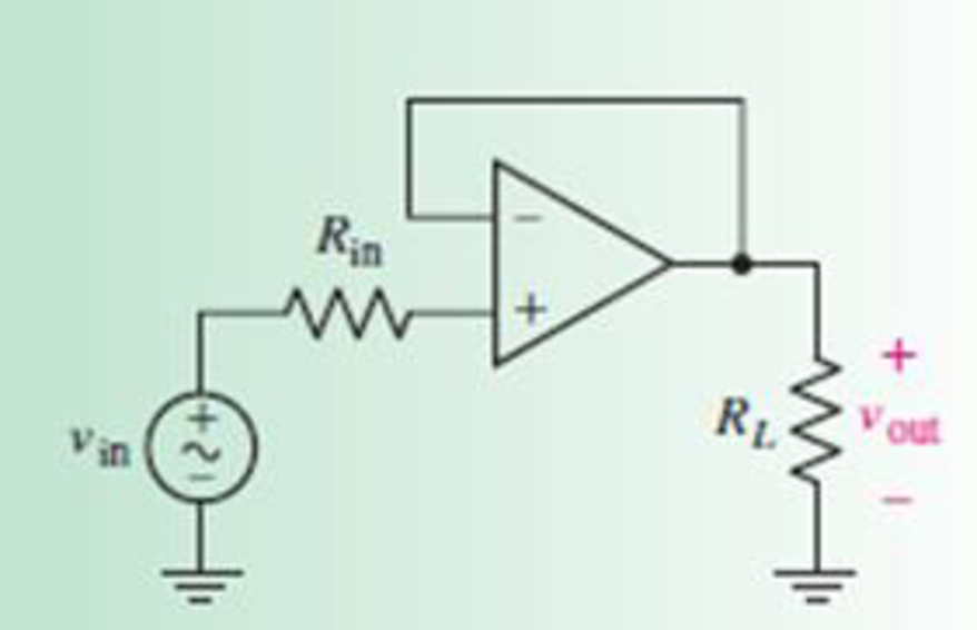
FIGURE 6.9
Expert Solution & Answer

Trending nowThis is a popular solution!

Students have asked these similar questions
P7.2
The capacitors in the circuit shown below have no energy stored in them and then switch "A"
closes at time t=0. Switch "B" closes 2.5 milliseconds later. Find v(t) across the 6 μF
capacitor for t≥ 0.
500 Ω
B
4 µF
20 V
6 µF 7
Σ2 ΚΩ
25 mA
+
· με
Q1: If x[n] is a discrete signal and represented by the following
equation, what is the value of x[0] and X[-2]
Q2:
{x[n]}={-0.2,2.2,1.1,0.2,-3.7,2.9,...}
a- Assuming that a 5-bit ADC channel accepts analog input ranging
from 0 to 4 volts, determine the following:
1- number of quantization levels;
2-step size of the quantizer or resolution;
3- quantization level when the analog voltage is 1.28 volts.
4- binary code produced by the ADC.
5- quantization error.
b- Determine whether the linear system is time invariant or not?
1 1
y(n) = x(n)
Q3: Evaluate the digital convolution of the following signals using
Graphical method. Find: y(0) to y(3)
Q4:
2, k = 0,1,2
2, k = 0
h(k)
0
1, k = 3,4 and x(k)
elsewhere
=
1,
k = 1,2
0
elsewhere
The temperature (in Kelvin) of an electronic component can be
modelled using the following approximation:
T(t) [293+15e-Ju(t)
A digital thermometer is used to periodically record the component's
temperature, taking a sample every 5 seconds.
1- Represent the…
I need solution by hand clearly
Chapter 6 Solutions
Loose Leaf for Engineering Circuit Analysis Format: Loose-leaf
Ch. 6.2 - Derive an expression for vout in terms of vin for...Ch. 6.2 - Prob. 2PCh. 6.3 - An historic bridge is showing signs of...Ch. 6.4 - Design a circuit that provides a 12 V output if a...Ch. 6.4 - Design a noninverting Schmitt trigger that that...Ch. 6.5 - Assuming a finite open-loop gain (A), a finite...Ch. 6.5 - Use SPICE to simulate a voltage follower using an...Ch. 6 - For the op amp circuit shown in Fig. 6.39,...Ch. 6 - FIGURE 6.39 Determine the power dissipated by a...Ch. 6 - For the circuit of Fig. 6.40, calculate vout if...
Ch. 6 - For the circuit in Fig. 6.40, find the values of...Ch. 6 - (a) Design a circuit which converts a voltage...Ch. 6 - Prob. 6ECh. 6 - For the circuit of Fig. 6.40, R1 = RL = 50 ....Ch. 6 - Prob. 8ECh. 6 - (a) Design a circuit using only a single op amp...Ch. 6 - Prob. 11ECh. 6 - Determine the output voltage v0 and the current...Ch. 6 - Prob. 13ECh. 6 - Prob. 14ECh. 6 - Prob. 15ECh. 6 - Prob. 16ECh. 6 - Consider the amplifier circuit shown in Fig. 6.46....Ch. 6 - Prob. 18ECh. 6 - Prob. 19ECh. 6 - Prob. 20ECh. 6 - Referring to Fig. 6.49, sketch vout as a function...Ch. 6 - Repeat Exercise 21 using a parameter sweep in...Ch. 6 - Obtain an expression for vout as labeled in the...Ch. 6 - Prob. 24ECh. 6 - Prob. 25ECh. 6 - Prob. 26ECh. 6 - Prob. 27ECh. 6 - Prob. 28ECh. 6 - Prob. 29ECh. 6 - Prob. 30ECh. 6 - Prob. 31ECh. 6 - Determine the value of Vout for the circuit in...Ch. 6 - Calculate V0 for the circuit in Fig. 6.55. FIGURE...Ch. 6 - Prob. 34ECh. 6 - The temperature alarm circuit in Fig. 6.56...Ch. 6 - Prob. 36ECh. 6 - For the circuit depicted in Fig. 6.57, sketch the...Ch. 6 - For the circuit depicted in Fig. 6.58, (a) sketch...Ch. 6 - For the circuit depicted in Fig. 6.59, sketch the...Ch. 6 - In digital logic applications, a +5 V signal...Ch. 6 - Using the temperature sensor in the circuit in...Ch. 6 - Examine the comparator Schmitt trigger circuit in...Ch. 6 - Design the circuit values for the single supply...Ch. 6 - For the instrumentation amplifier shown in Fig....Ch. 6 - A common application for instrumentation...Ch. 6 - (a) Employ the parameters listed in Table 6.3 for...Ch. 6 - Prob. 49ECh. 6 - For the circuit of Fig. 6.62, calculate the...Ch. 6 - Prob. 51ECh. 6 - FIGURE 6.63 (a) For the circuit of Fig. 6.63, if...Ch. 6 - The difference amplifier circuit in Fig. 6.32 has...Ch. 6 - Prob. 55ECh. 6 - Prob. 56ECh. 6 - Prob. 57ECh. 6 - Prob. 58ECh. 6 - Prob. 59ECh. 6 - Prob. 60ECh. 6 - A fountain outside a certain office building is...Ch. 6 - For the circuit of Fig. 6.44, let all resistor...
Additional Engineering Textbook Solutions
Find more solutions based on key concepts
Which of the following are illegal variable names in Python, and why? x 99bottles july2009 theSalesFigureForFis...
Starting Out with Python (4th Edition)
This optional Google account security feature sends you a message with a code that you must enter, in addition ...
SURVEY OF OPERATING SYSTEMS
A nozzle at A discharges water with an initial velocity of 36 ft/s at an angle with the horizontal. Determine ...
Vector Mechanics For Engineers
What is an uninitialized variable?
Starting Out with Programming Logic and Design (5th Edition) (What's New in Computer Science)
How does a computers main memory differ from its auxiliary memory?
Java: An Introduction to Problem Solving and Programming (8th Edition)
Convert each of the following binary representations to its equivalent base ten form: a. 101010 b. 100001 c. 10...
Computer Science: An Overview (13th Edition) (What's New in Computer Science)
Knowledge Booster


Learn more about
Need a deep-dive on the concept behind this application? Look no further. Learn more about this topic, electrical-engineering and related others by exploring similar questions and additional content below.Similar questions
- fin D Q Point 7.57 in Matlab Aarrow_forwardFor the following graphical figure, write the function x(n) and h(n) in: 1. sequential vector 2. functional representation 3. Tabular 2 h0) 32 If signal x(n)-(32130 104032)], describe this signal using: 1. Graphical representation 2. Tabular representation 3. Write its expression 4. Write it as equation 5. Draw it as y(n) - x(n) u(n-3) 6. Sketch it if it is bounded at -2arrow_forwardFor the following Split-phase Manchester waveform, extract the original binary data. Then draw the AMI code for that data. 0arrow_forward1 ΚΩ N₁ m ZL (10+j4) ks2 178/0° V N2 -202 Ω Figure P11.31 Circuit for Problem 11.31.arrow_forwardCari induktasi saluran transmisi terhadapku GMDarrow_forwardA wattmeter is connected with the positive lead on phase “a” of a three-phase system. The negative lead is connected to phase “b”. A separate wattmeter has the positive lead connected to phase “c”. The negative lead of this wattmeter is connected also to phase “b”. If the input voltage is 208 volts line-to-line, the phase sequence is “abc” and the load is 1200 ohm resistors connected in “Y”, what is the expected reading of each of the wattmeters? (Hint: draw a phasor diagram)arrow_forwarda b 1 ΚΩΣ 56002 82092 470Ω Rab, Rbc, Rde d e O 470Ω Σ 5 Ω 25$ 5602 3 4 Ωarrow_forwardMY code is experiencing a problem as I want to show both the magnitude ratio on low pass, high pass, and bandbass based on passive filters: Code: % Define frequency range for the plot f = logspace(1, 5, 500); % Frequency range from 10 Hz to 100 kHz w = 2*pi*f; % Angular frequency % Parameters for the filters (you can modify these) R = 1e3; % Resistance in ohms (1 kOhm) C = 1e-6; % Capacitance in farads (1 uF) L = 10e-3; % Inductance in henries (10 mH) % Transfer function for Low-pass filter: H_low = 1 / (1 + jωRC) H_low = 1 ./ (1 + 1i*w*R*C); % Transfer function for High-pass filter: H_high = jωRC / (1 + jωRC) H_high = 1i*w*R*C ./ (1 + 1i*w*R*C); % Transfer function for Band-pass filter: H_band = jωRC / (1 + jωL/R + jωRC) H_band = 1i*w*R*C ./ (1 + 1i*w*L/R + 1i*w*R*C); % Plot magnitude responses figure; subplot(3,1,1); semilogx(f, 20*log10(abs(H_low))); % Low-pass filter title('Magnitude Response of Low-pass Filter'); xlabel('Frequency (Hz)'); ylabel('Magnitude (dB)'); grid…arrow_forward*10. For the network of Fig. 7.83, determine: a. Ip. b. VDS. c. VD. d. Vs. 20 V 2.2 ΚΩ ID -4 V IDSS = 4.5 mA VDS Vp = -5V 0.68 ΚΩarrow_forwardarrow_back_iosSEE MORE QUESTIONSarrow_forward_ios
Recommended textbooks for you
 Introductory Circuit Analysis (13th Edition)Electrical EngineeringISBN:9780133923605Author:Robert L. BoylestadPublisher:PEARSON
 Delmar's Standard Textbook Of ElectricityElectrical EngineeringISBN:9781337900348Author:Stephen L. HermanPublisher:Cengage Learning
 Programmable Logic ControllersElectrical EngineeringISBN:9780073373843Author:Frank D. PetruzellaPublisher:McGraw-Hill Education
 Fundamentals of Electric CircuitsElectrical EngineeringISBN:9780078028229Author:Charles K Alexander, Matthew SadikuPublisher:McGraw-Hill Education
 Electric Circuits. (11th Edition)Electrical EngineeringISBN:9780134746968Author:James W. Nilsson, Susan RiedelPublisher:PEARSON
 Engineering ElectromagneticsElectrical EngineeringISBN:9780078028151Author:Hayt, William H. (william Hart), Jr, BUCK, John A.Publisher:Mcgraw-hill Education,
Introductory Circuit Analysis (13th Edition)
Electrical Engineering
ISBN:9780133923605
Author:Robert L. Boylestad
Publisher:PEARSON
Delmar's Standard Textbook Of Electricity
Electrical Engineering
ISBN:9781337900348
Author:Stephen L. Herman
Publisher:Cengage Learning
Programmable Logic Controllers
Electrical Engineering
ISBN:9780073373843
Author:Frank D. Petruzella
Publisher:McGraw-Hill Education
Fundamentals of Electric Circuits
Electrical Engineering
ISBN:9780078028229
Author:Charles K Alexander, Matthew Sadiku
Publisher:McGraw-Hill Education
Electric Circuits. (11th Edition)
Electrical Engineering
ISBN:9780134746968
Author:James W. Nilsson, Susan Riedel
Publisher:PEARSON
Engineering Electromagnetics
Electrical Engineering
ISBN:9780078028151
Author:Hayt, William H. (william Hart), Jr, BUCK, John A.
Publisher:Mcgraw-hill Education,
Peripheral Pin Select (PPS) for Microchip 8-bit PIC MCU; Author: Microchip Technology;https://www.youtube.com/watch?v=tf2SfSm6fQg;License: Standard Youtube License