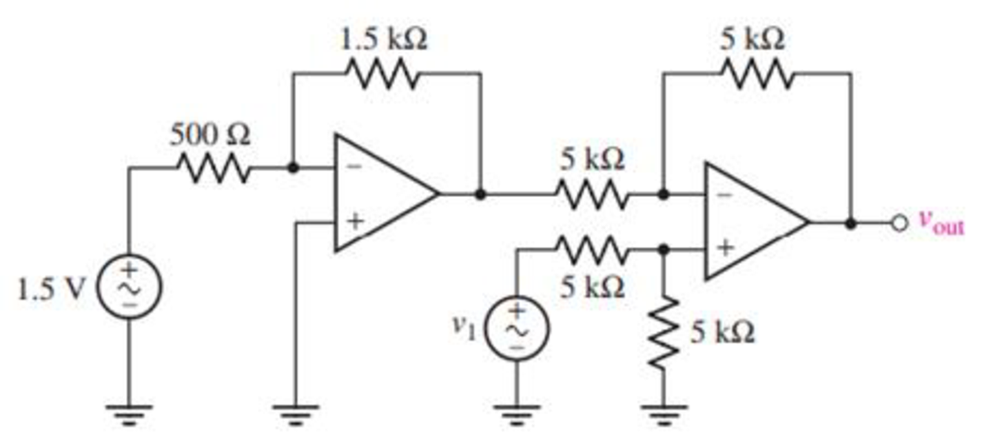
Obtain an expression for vout as labeled in the circuit of Fig. 6.50 if v1 equals (a) 0 V; (b) 1 V; (c) −5 V; (d) 2 sin 100t V.

FIGURE 6.50
(a)
Find the output voltage
Answer to Problem 23E
The output voltage
Explanation of Solution
Given data:
The input voltage
Calculation:
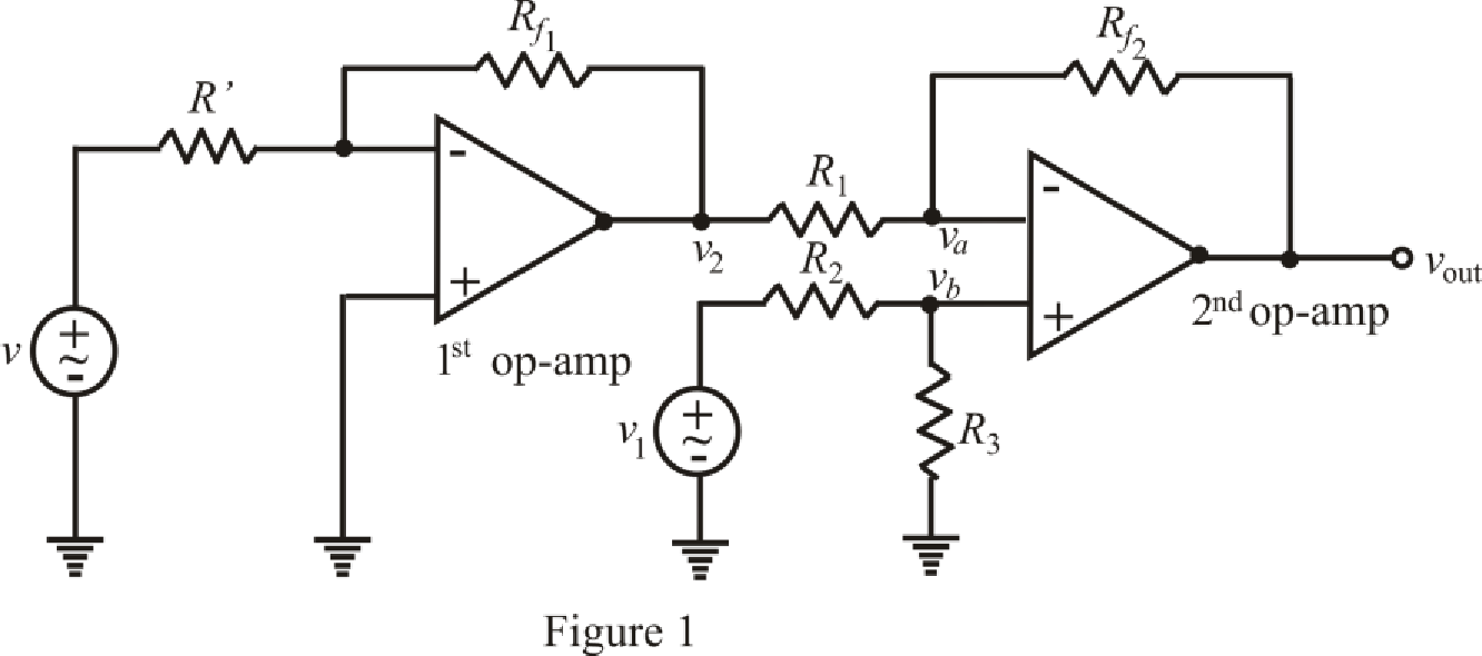
The redrawn circuit is shown in Figure 1 as follows.

Refer to the Figure 1.
The expression of output voltage for 1st inverting op amp is,
Here,
The expression by the nodal analysis at node
Here,
The expression by the nodal analysis at node
Here,
The expression for the virtual ground concept is as follows,
Refer to the redrawn Figure 1.
Simplify equation (2) as follows.
Rearrange equation (3) for
Substitute
Rearrange for
Substitute for
Substitute
Conclusion:
Thus, the output voltage
(b)
Find the output voltage
Answer to Problem 23E
The output voltage
Explanation of Solution
Given data:
Value of input voltage
Calculation:
Refer to the redrawn Figure 1.
Substitute
Solve for
Conclusion:
Thus, the output voltage
(c)
Find the output voltage
Answer to Problem 23E
The output voltage
Explanation of Solution
Given data:
Value of input voltage
Calculation:
Refer to the redrawn Figure 1.
Substitute
Solve for
Conclusion:
Thus, the output voltage
(d)
Find the output voltage
Answer to Problem 23E
The output voltage
Explanation of Solution
Given data:
Value of input voltage
Calculation:
Refer to the redrawn Figure 1.
Substitute
Solve for
Conclusion:
Thus, the output voltage
Want to see more full solutions like this?
Chapter 6 Solutions
Loose Leaf for Engineering Circuit Analysis Format: Loose-leaf
- According to the book the answers are m= 30 and n = 5 and number of switch blocks is 220arrow_forwardfind reactive power demand , capacitor bank provides and overcompenstationarrow_forward(A) Consider a communication system where the number of successful transsions out of 10 trials follows a binomial distribution. The success probability for each triat is 0,95, Let X be the random variable representing the number of successful transmissions. -Sketch the cumulative distribution function (CDF) of the distribution. 2- Find Skewness coefficients and check if the distribution is symmetrical or skewed to the right or left. 3- Find kurtosis coefficients, Check if the distribution is mesokurtic, leptokurtic or platykurtic. 4- Find the probability of getting at most eigh. successful transmissions. 5- Find the probability P(20 with a mean 2-1 calculate the probability that the noise is greater than 3 units.arrow_forward
- Q4: (A) Find the mean of a random variable X if S f(x)= 2x 0 2 for 0arrow_forward(A) Suopces the current measurements in a strip of wire are normally distributed with ca-10(mA) and a varieocom (mA)² 1- What is the probability that a current measurement lies between 7.4 and 11.6 mA? 2-Drew the probability density function of the current distribution. (8) A factory produces light bulbs with a koown probability of P(D)-0.08 that & bulo is dalective. If a bulb is defective, the probability that the quality control test detects it is defective is P(TID)-0.90. Conversely, if a bulb is not defective, the probability that the test Telesly indicaton k as defective is P(TID)-0.05. calculate the probability that a light b is notually defective given that the test result is positive, F(DIT).arrow_forwardTitle: Modelling and Simulating Boost Converter Battery Charging Powered by PV Solar Question: I need a MATLAB/Simulink model for a Boost Converter used to charge a battery, powered by a PV solar panel. The model should include: 1. A PV solar panel as the input power source. 2. A Boost Converter circuit for voltage regulation. 3. A battery charging system. 4. Simulation results showing voltage, current, and efficiency of the system. Please provide the Simulink file and any necessary explanations.arrow_forwardarrow_back_iosSEE MORE QUESTIONSarrow_forward_ios
 Introductory Circuit Analysis (13th Edition)Electrical EngineeringISBN:9780133923605Author:Robert L. BoylestadPublisher:PEARSON
 Delmar's Standard Textbook Of ElectricityElectrical EngineeringISBN:9781337900348Author:Stephen L. HermanPublisher:Cengage Learning
 Programmable Logic ControllersElectrical EngineeringISBN:9780073373843Author:Frank D. PetruzellaPublisher:McGraw-Hill Education
 Fundamentals of Electric CircuitsElectrical EngineeringISBN:9780078028229Author:Charles K Alexander, Matthew SadikuPublisher:McGraw-Hill Education
 Electric Circuits. (11th Edition)Electrical EngineeringISBN:9780134746968Author:James W. Nilsson, Susan RiedelPublisher:PEARSON
 Engineering ElectromagneticsElectrical EngineeringISBN:9780078028151Author:Hayt, William H. (william Hart), Jr, BUCK, John A.Publisher:Mcgraw-hill Education,


