
Concept explainers
Videos
A common application for instrumentation amplifiers is to measure voltages in resistive strain gauge circuits. These strain sensors work by exploiting the changes in resistance that result from geometric distortions, as in Eq. [6] of Chap. 2. They are often part of a bridge circuit, as shown in Fig. 6.61a, where the strain gauge is identified as RG. (a) Show that
AD622 Specifications
Amplifier gain G can be varied from 2 to 1000 by connecting a resistor Between pins 1 and 8 with a value calculated by
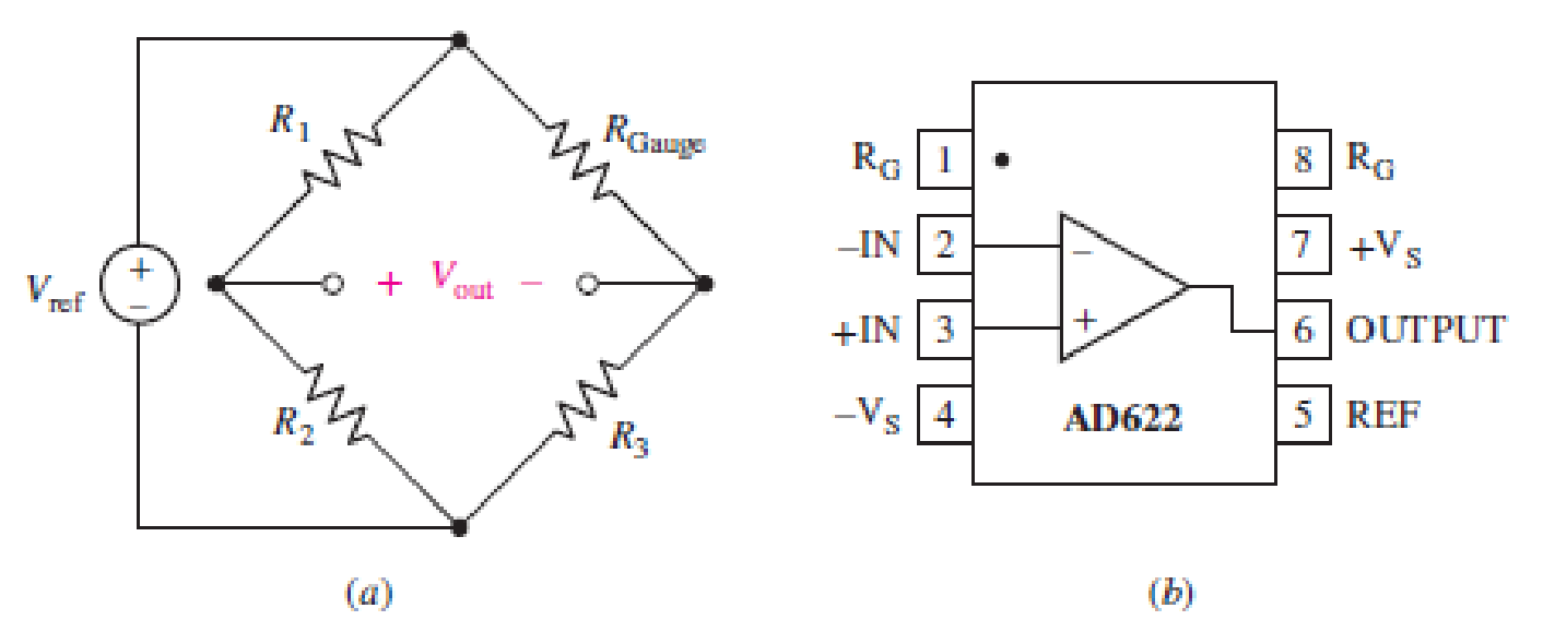
FIGURE 6.61
Want to see the full answer?
Check out a sample textbook solution
Chapter 6 Solutions
Loose Leaf for Engineering Circuit Analysis Format: Loose-leaf


- Can you solve for V1 and V2arrow_forwardyou dont need to solve the question i just wanna know the steps and how to find the angle between the voltage difference and the current . thanks so mucharrow_forwardistics of diodes, bipolar junction transistors, and plain the structure, operation, 1. The purpose of doping in semiconductor diodes is: a) To control their electrical properties b) To increase their physical size c) To enhance their mechanical strength d) To improve their thermal stability 2. In electronics production, your team wants to manufacture a very cheap diode rectifier. Which of the following rectifier configurations would you select? a) Half-wave rectifier c) Full-wave rectifier b) Bridge rectifier d) Controlled rectifier 3. The region that a Zener diode operates to provide voltage regulation is: a) Saturation c) Reverse bias b) Breakdown d) Forward bias 4. In NMOS transistors, the depth of the channel is primarily changed by: a) VDS b) lp c) VGS d) None of these 5. NMOS transistors have than PMOS, resulting in better current conduction: b) Long channel a) High mobility c) Low mobility d) Short channel 6. You are working in electronic production, and your team is asked to…arrow_forward
- 8.46 The generator circuit shown in Fig. P8.46 (on page 494) isconnected to a distant load via a long coaxial transmission line.The overall circuit can be modeled as in Fig. P8.46(b), in whichthe transmission line is represented by an equivalent impedanceZline = (5+ j2) W.(a) Determine the power factor of voltage source Vs.(b) Specify the capacitance of a shunt capacitor C that wouldraise the power factor of the source to unity when connectedbetween terminals (a,b). The source frequency is 1.5 kHz.arrow_forward7. MOSFET circuit The MOSFET in the circuit below has V₁ = 1 V and kn = 4 mA/V². a) Is the MOSFET operating in saturation or in the triode region? b) Determine the drain current ID and Vout. + 5 V 5 k Voutarrow_forwardDraw a logic diagram of a 4-bit adder/subtractor then use it to design an Exess-3 to BCD code converter circuit. The circuit has an input (x4 xs x2x) and output (ye ya ya yi)scrarrow_forward
- If waveforms shown in figure below are applied as inputs to a 2-bit comparator (P=P: Po and Q=Q: Q), draw the three output waveforms of the comparator (P>Q, P=Q, Parrow_forwardmicro wavearrow_forwardmicro wavearrow_forwardFor this question, please show how to get the answer using block diagrams. I have included my attempt but I am not close to the answer and I don't understand how to get the T_d(s) expression. Please show the block diagram steps, as in, do not just plug this question into an AI. thank youarrow_forwardOnly expert should attempt this questions, handwritten solution onlyarrow_forwardPlease show formula used and steps as I will study themarrow_forwardarrow_back_iosSEE MORE QUESTIONSarrow_forward_ios
 Delmar's Standard Textbook Of ElectricityElectrical EngineeringISBN:9781337900348Author:Stephen L. HermanPublisher:Cengage Learning