
Loose Leaf for Engineering Circuit Analysis Format: Loose-leaf
9th Edition
ISBN: 9781259989452
Author: Hayt
Publisher: Mcgraw Hill Publishers
expand_more
expand_more
format_list_bulleted
Videos
Textbook Question
thumb_up100%
Chapter 6, Problem 35E
The temperature alarm circuit in Fig. 6.56 utilizes a temperature sensor whose resistance changes according to R = 80[1 + α(T − 25)] Ω, where T is the temperature in Celsius and α is the temperature sensitivity with a value of 0.004/°C. Determine the output vout as a function of temperature.
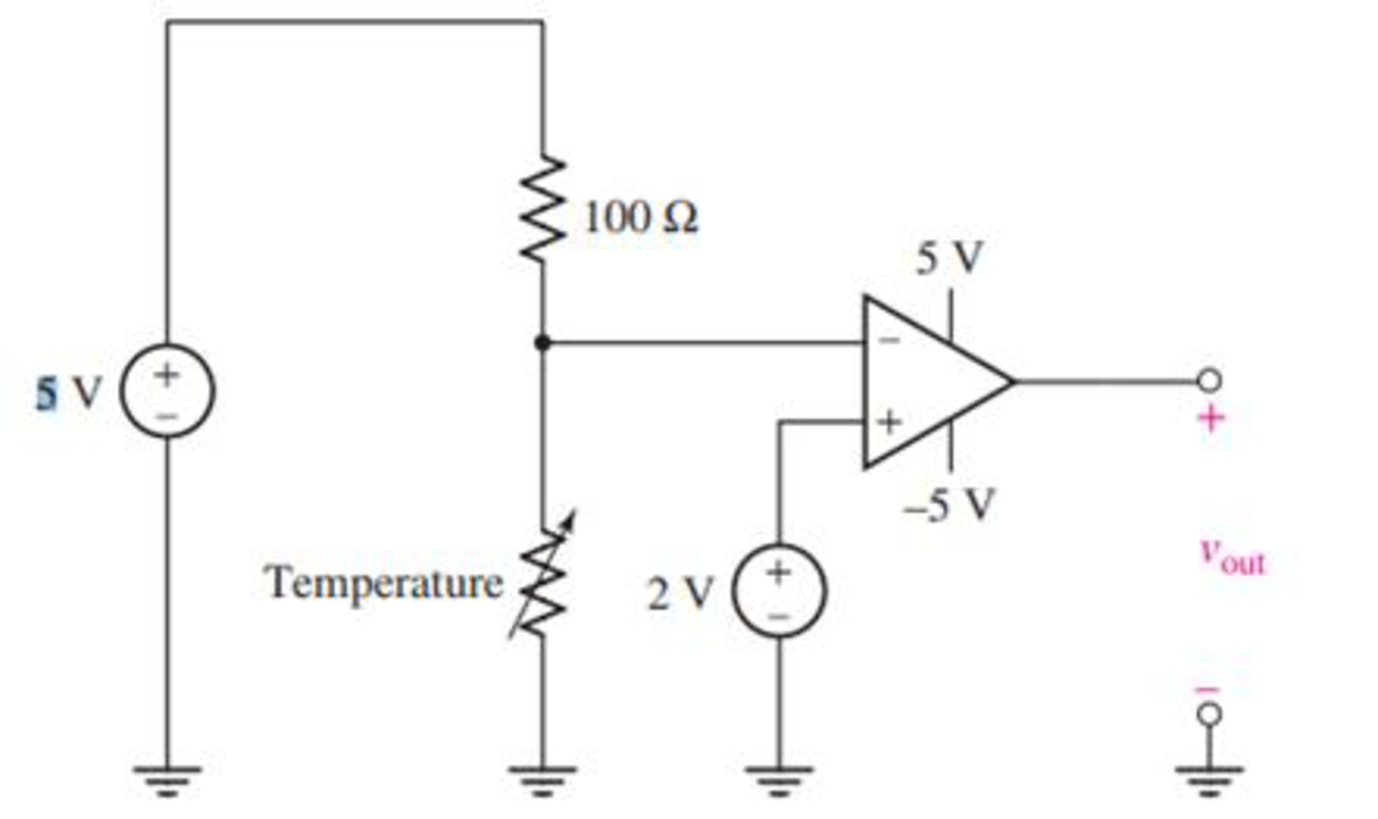
FIGURE 6.56
Expert Solution & Answer
Want to see the full answer?
Check out a sample textbook solution
Students have asked these similar questions
NO AI PLEASE
I need help with this problem and an explanation of the solution for the image described below. (Introduction to Signals and Systems)
NO AI PLEASE.
Chapter 6 Solutions
Loose Leaf for Engineering Circuit Analysis Format: Loose-leaf
Ch. 6.2 - Derive an expression for vout in terms of vin for...Ch. 6.2 - Prob. 2PCh. 6.3 - An historic bridge is showing signs of...Ch. 6.4 - Design a circuit that provides a 12 V output if a...Ch. 6.4 - Design a noninverting Schmitt trigger that that...Ch. 6.5 - Assuming a finite open-loop gain (A), a finite...Ch. 6.5 - Use SPICE to simulate a voltage follower using an...Ch. 6 - For the op amp circuit shown in Fig. 6.39,...Ch. 6 - FIGURE 6.39 Determine the power dissipated by a...Ch. 6 - For the circuit of Fig. 6.40, calculate vout if...
Ch. 6 - For the circuit in Fig. 6.40, find the values of...Ch. 6 - (a) Design a circuit which converts a voltage...Ch. 6 - Prob. 6ECh. 6 - For the circuit of Fig. 6.40, R1 = RL = 50 ....Ch. 6 - Prob. 8ECh. 6 - (a) Design a circuit using only a single op amp...Ch. 6 - Prob. 11ECh. 6 - Determine the output voltage v0 and the current...Ch. 6 - Prob. 13ECh. 6 - Prob. 14ECh. 6 - Prob. 15ECh. 6 - Prob. 16ECh. 6 - Consider the amplifier circuit shown in Fig. 6.46....Ch. 6 - Prob. 18ECh. 6 - Prob. 19ECh. 6 - Prob. 20ECh. 6 - Referring to Fig. 6.49, sketch vout as a function...Ch. 6 - Repeat Exercise 21 using a parameter sweep in...Ch. 6 - Obtain an expression for vout as labeled in the...Ch. 6 - Prob. 24ECh. 6 - Prob. 25ECh. 6 - Prob. 26ECh. 6 - Prob. 27ECh. 6 - Prob. 28ECh. 6 - Prob. 29ECh. 6 - Prob. 30ECh. 6 - Prob. 31ECh. 6 - Determine the value of Vout for the circuit in...Ch. 6 - Calculate V0 for the circuit in Fig. 6.55. FIGURE...Ch. 6 - Prob. 34ECh. 6 - The temperature alarm circuit in Fig. 6.56...Ch. 6 - Prob. 36ECh. 6 - For the circuit depicted in Fig. 6.57, sketch the...Ch. 6 - For the circuit depicted in Fig. 6.58, (a) sketch...Ch. 6 - For the circuit depicted in Fig. 6.59, sketch the...Ch. 6 - In digital logic applications, a +5 V signal...Ch. 6 - Using the temperature sensor in the circuit in...Ch. 6 - Examine the comparator Schmitt trigger circuit in...Ch. 6 - Design the circuit values for the single supply...Ch. 6 - For the instrumentation amplifier shown in Fig....Ch. 6 - A common application for instrumentation...Ch. 6 - (a) Employ the parameters listed in Table 6.3 for...Ch. 6 - Prob. 49ECh. 6 - For the circuit of Fig. 6.62, calculate the...Ch. 6 - Prob. 51ECh. 6 - FIGURE 6.63 (a) For the circuit of Fig. 6.63, if...Ch. 6 - The difference amplifier circuit in Fig. 6.32 has...Ch. 6 - Prob. 55ECh. 6 - Prob. 56ECh. 6 - Prob. 57ECh. 6 - Prob. 58ECh. 6 - Prob. 59ECh. 6 - Prob. 60ECh. 6 - A fountain outside a certain office building is...Ch. 6 - For the circuit of Fig. 6.44, let all resistor...
Knowledge Booster


Learn more about
Need a deep-dive on the concept behind this application? Look no further. Learn more about this topic, electrical-engineering and related others by exploring similar questions and additional content below.Similar questions
- 2-3) For each of the two periodic signals in the figures below, find the exponential Fourier series and sketch the magnitude and angle spectra. -5 ΟΙ 1 1- (a) (b) -20π -10x -π Π 10m 20m 1-arrow_forwardI need help with this problem and an explanation of the solution for the image described below. (Introduction to Signals and Systems)arrow_forwardIn the op-amp circuit shown in Fig. P8.32,uin(t) = 12cos(1000t) V,R = 10 k Ohm , RL = 5 k Ohm, and C = 1 μF. Determine the complexpower for each of the passive elements in the circuit. Isconservation of energy satisfied?arrow_forward
- 2-4) Similar to Lathi & Ding prob. 2.9-4 (a) For signal g(t)=t, find the exponential Fourier series to represent g(t) over the interval(0, 1). (b) Sketch the original signal g(t) and the everlasting signal g'(t) represented by the same Fourier series. (c) Verify Parseval's theorem [eq. (2.103b)] for g'(t), given that: = n 1 6arrow_forward8.24 In the circuit of Fig. P8.24, is(t) = 0.2sin105t A,R = 20 W, L = 0.1 mH, and C = 2 μF. Show that the sum ofthe complex powers for the three passive elements is equal to thecomplex power of the source.arrow_forward3. VEB (on) 0.7 V, VEC (sat) = 0.2 V, and ẞ = 150. RB = 50 kQ, Rc = 2 kQ, and Vcc = 5 V. a) Find the range of V₁ for the cut-off. Forward active, and saturation regions. (20 points) b) Draw the voltage transfer characteristic (VTC) graph. (10 points) Vcc VEB V₁ RB www 。 Vo Rc Figure 3arrow_forward
- 2-1) Lathi & Ding prob. 2.5-2 For the signals y(t) and x(t) shown below, find the component of the form y(t) contained in x(t). In other words, find the optimum value of c in the approximation x(t) = cy(t) so that the error signal energy is minimum. Also compute the error signal energy. y(t) x(t) 0 1 0 1arrow_forward1. Is1 = 2ls2 = 4 × 10-16 A, B₁ = ẞ2 = 100, and R₁ = 5 kQ. Find the VB such that lx = 1 mA. (30 points) R1 ww Q2 + VB Figure 1arrow_forward2-2) Lathi & Ding prob. 2.6-1 2.6-1 Find the correlation coefficient p between of signal x(t) and each of the four pulses g1(1), 82(1), 83(1), and g4(f) shown in Fig. P2.6-1. To provide maximum margin against the noise along the transmission path, which pair of pulses would you select for a binary communication? Figure P.2.6-1 x(f) (a) 8(1) (b) 82(1) (c) 1 1 sin 2πt sin 4πt -sin 2 0 0.707 83(1) 0 1 (d) 0 M P 0.707 84(1) (e) 0 0.5 -0.707arrow_forward
- 2. Determine the operation point and the small-signal model of Q₁ for each of the circuits shown in Fig. 2. Assume Is = 8 × 10-16 A, B = 100 and VA = ∞. a) 20 points b) 20 points 0.8 V RC 50 Ω + Vcc = 2.5 V 4A" Figure 2-a Rc1kQ + Vcc = 2.5 V Figure 2-barrow_forwardPlease explain in detail how to solve this question. Show detailed steps in terms of calculation and theory. thank youarrow_forwardPls show neat and whole solutionarrow_forward
arrow_back_ios
SEE MORE QUESTIONS
arrow_forward_ios
Recommended textbooks for you
 Introductory Circuit Analysis (13th Edition)Electrical EngineeringISBN:9780133923605Author:Robert L. BoylestadPublisher:PEARSON
 Delmar's Standard Textbook Of ElectricityElectrical EngineeringISBN:9781337900348Author:Stephen L. HermanPublisher:Cengage Learning
 Programmable Logic ControllersElectrical EngineeringISBN:9780073373843Author:Frank D. PetruzellaPublisher:McGraw-Hill Education
 Fundamentals of Electric CircuitsElectrical EngineeringISBN:9780078028229Author:Charles K Alexander, Matthew SadikuPublisher:McGraw-Hill Education
 Electric Circuits. (11th Edition)Electrical EngineeringISBN:9780134746968Author:James W. Nilsson, Susan RiedelPublisher:PEARSON
 Engineering ElectromagneticsElectrical EngineeringISBN:9780078028151Author:Hayt, William H. (william Hart), Jr, BUCK, John A.Publisher:Mcgraw-hill Education,
Introductory Circuit Analysis (13th Edition)
Electrical Engineering
ISBN:9780133923605
Author:Robert L. Boylestad
Publisher:PEARSON
Delmar's Standard Textbook Of Electricity
Electrical Engineering
ISBN:9781337900348
Author:Stephen L. Herman
Publisher:Cengage Learning
Programmable Logic Controllers
Electrical Engineering
ISBN:9780073373843
Author:Frank D. Petruzella
Publisher:McGraw-Hill Education
Fundamentals of Electric Circuits
Electrical Engineering
ISBN:9780078028229
Author:Charles K Alexander, Matthew Sadiku
Publisher:McGraw-Hill Education
Electric Circuits. (11th Edition)
Electrical Engineering
ISBN:9780134746968
Author:James W. Nilsson, Susan Riedel
Publisher:PEARSON
Engineering Electromagnetics
Electrical Engineering
ISBN:9780078028151
Author:Hayt, William H. (william Hart), Jr, BUCK, John A.
Publisher:Mcgraw-hill Education,
Inductors Explained - The basics how inductors work working principle; Author: The Engineering Mindset;https://www.youtube.com/watch?v=KSylo01n5FY;License: Standard Youtube License