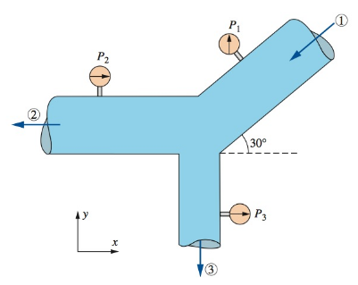
Water flows steadily through a splitter as shown in Fig. P6−97 with

FIGURE P6−97
The external force needed to hold the device fixed.
Answer to Problem 97P
The final resultant force
Explanation of Solution
Given information:
The pressure at pipe
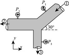
The following figure represents the water flows steadily through a splitter.

Figure (1)
Write the expression for the cross-sectional area of pipe
Here, the area of pipe
Write the expression for the cross-sectional area of pipe
Here, the area of pipe
Write the expression for the cross-sectional area of pipe
Here, the area of pipe
Write the expression for the velocity of flow in the pipe
Here, the velocity of flow in the pipe
Write the expression for the velocity of flow in the pipe
Here, the velocity of flow in the pipe
Write the expression for the velocity of flow in the pipe
Here, the velocity of flow in pipe
Write the expression for resultant force for
Here, the resultant force foe
Write the expression for resultant force for
Here, the resultant force for
Write the expression for net resultant force.
Here, the net resultant force is
Write the expression for angle of application of force.
Here, the angle of application is
Calculation:
Substitute
Substitute
Substitute
Substitute
Substitute
Substitute
Substitute
Substitute
Substitute
Thus, the final resultant force is
Substitute
The final resultant force
Conclusion:
The final resultant force
Want to see more full solutions like this?
Chapter 6 Solutions
Fluid Mechanics Fundamentals And Applications
- 5. Estimate the friction pressure gradient in a 10.15 cm bore unheated horizontal pipe for the following conditions: Fluid-propylene Pressure 8.175 bar Temperature-7°C Mass flow of liquid-2.42 kg/s. Density of liquid-530 kg/m³ Mass flow of vapour-0.605 kg/s. Density of vapour-1.48 kg/m³arrow_forwardDescribe the following HVAC systems. a) All-air systems b) All-water systems c) Air-water systems Graphically represent each system with a sketch.arrow_forwardTwo large tanks, each holding 100 L of liquid, are interconnected by pipes, with the liquid flowing from tank A into tank B at a rate of 3 L/min and from B into A at a rate of 1 L/min (see Figure Q1). The liquid inside each tank is kept well stirred. A brine solution with a concentration of 0.2 kg/L of salt flows into tank A at a rate of 6 L/min. The diluted solution flows out of the system from tank A at 4 L/min and from tank B at 2 L/min. If, initially, tank A contains pure water and tank B contains 20 kg of salt. A 6 L/min 0.2 kg/L x(t) 100 L 4 L/min x(0) = 0 kg 3 L/min 1 L/min B y(t) 100 L y(0) = 20 kg 2 L/min Figure Q1 - Mixing problem for interconnected tanks Determine the mass of salt in each tank at time t≥ 0: Analytically (hand calculations) Using MATLAB Numerical Functions (ode45) Creating Simulink Model Plot all solutions on the same graph for the first 15 min. The graph must be fully formatted by code.arrow_forward
- ased on the corresponding mass flow rates (and NOT the original volumetric flow rates) determine: a) The mass flow rate of the mixed air (i.e., the combination of the two flows) leaving the chamber in kg/s. b) The temperature of the mixed air leaving the chamber. Please use PyscPro software for solving this question. Notes: For part (a), you will first need to find the density or specific volume for each state (density = 1/specific volume). The units the 'v' and 'a' are intended as subscripts: · kgv = kg_v = kgv = kilogram(s) [vapour] kga = kg_a =kga = kilogram(s) [air]arrow_forwardThe answers to this question s wasn't properly given, I need expert handwritten solutionsarrow_forwardI need expert handwritten solutions to this onlyarrow_forward
- Two large tanks, each holding 100 L of liquid, are interconnected by pipes, with the liquid flowing from tank A into tank B at a rate of 3 L/min and from B into A at a rate of 1 L/min (see Figure Q1). The liquid inside each tank is kept well stirred. A brine solution with a concentration of 0.2 kg/L of salt flows into tank A at a rate of 6 L/min. The diluted solution flows out of the system from tank A at 4 L/min and from tank B at 2 L/min. If, initially, tank A contains pure water and tank B contains 20 kg of salt. A 6 L/min 0.2 kg/L x(t) 100 L 4 L/min x(0) = 0 kg 3 L/min B y(t) 100 L y(0) = 20 kg 2 L/min 1 L/min Figure Q1 - Mixing problem for interconnected tanks Determine the mass of salt in each tank at time t > 0: Analytically (hand calculations)arrow_forwardTwo springs and two masses are attached in a straight vertical line as shown in Figure Q3. The system is set in motion by holding the mass m₂ at its equilibrium position and pushing the mass m₁ downwards of its equilibrium position a distance 2 m and then releasing both masses. if m₁ = m₂ = 1 kg, k₁ = 3 N/m and k₂ = 2 N/m. www.m k₁ = 3 (y₁ = 0). m₁ = 1 k2=2 (y₂ = 0) |m₂ = 1 Y2 y 2 System in static equilibrium (Net change in spring length =32-31) System in motion Figure Q3 - Coupled mass-spring system Determine the equations of motion y₁(t) and y₂(t) for the two masses m₁ and m₂ respectively: Analytically (hand calculations)arrow_forward100 As a spring is heated, its spring constant decreases. Suppose the spring is heated and then cooled so that the spring constant at time t is k(t) = t sin N/m. If the mass-spring system has mass m = 2 kg and a damping constant b = 1 N-sec/m with initial conditions x(0) = 6 m and x'(0) = -5 m/sec and it is subjected to the harmonic external force f(t) = 100 cos 3t N. Find at least the first four nonzero terms in a power series expansion about t = 0, i.e. Maclaurin series expansion, for the displacement: Analytically (hand calculations)arrow_forward
- this is answer to a vibrations question. in the last part it states an assumption of x2, im not sure where this assumption comes from. an answer would be greatly appreciatedarrow_forwardPlease answer with the sketches.arrow_forwardThe beam is made of elastic perfectly plastic material. Determine the shape factor for the cross section of the beam (Figure Q3). [Take σy = 250 MPa, yNA = 110.94 mm, I = 78.08 x 106 mm²] y 25 mm 75 mm I 25 mm 200 mm 25 mm 125 Figure Q3arrow_forward
 Elements Of ElectromagneticsMechanical EngineeringISBN:9780190698614Author:Sadiku, Matthew N. O.Publisher:Oxford University Press
 Mechanics of Materials (10th Edition)Mechanical EngineeringISBN:9780134319650Author:Russell C. HibbelerPublisher:PEARSON
 Thermodynamics: An Engineering ApproachMechanical EngineeringISBN:9781259822674Author:Yunus A. Cengel Dr., Michael A. BolesPublisher:McGraw-Hill Education
 Control Systems EngineeringMechanical EngineeringISBN:9781118170519Author:Norman S. NisePublisher:WILEY
 Mechanics of Materials (MindTap Course List)Mechanical EngineeringISBN:9781337093347Author:Barry J. Goodno, James M. GerePublisher:Cengage Learning
 Engineering Mechanics: StaticsMechanical EngineeringISBN:9781118807330Author:James L. Meriam, L. G. Kraige, J. N. BoltonPublisher:WILEY


